
led dimmer circuit

The LED dimmer circuit employs the LM317T voltage regulator, which is versatile due to its ability to regulate both voltage and current. This characteristic is particularly useful in LED applications where consistent brightness is required. The circuit is designed to accommodate ten super bright white LEDs, allowing for flexibility in the number of LEDs used based on specific lighting needs.
The variable resistor, rated at 200 ohms, serves as a means to adjust the LED brightness by varying the current flowing through the circuit. By changing the resistance, the user can effectively control the luminosity of the LEDs, making this circuit suitable for applications where adjustable lighting is beneficial.
Each LED in the circuit is paired with a current-limiting resistor. This design choice is critical, as it prevents excessive current from damaging the LEDs. The LM317T can supply a maximum current of 1.5A, which is adequate for driving multiple LEDs. However, to ensure longevity and reliability, the inclusion of individual current-limiting resistors for each LED is essential. These resistors are calculated based on the forward voltage and current specifications of the LEDs used, ensuring that each LED operates within its safe limits.
Overall, this LED dimmer circuit is a practical solution for those seeking to create adjustable lighting with super bright LEDs, leveraging the capabilities of the LM317T voltage regulator for optimal performance and safety.Here is a very easy and useful schematic of an LED dimmer circuit. The circuit is using a famous voltage regulator IC LM317T. This IC can also be used as a current regulator, like it is used in the following circuit. In this circuit we have used 10 super bright white LEDs, but the number of LEDs can be increase if desired. The 200 ohms variable r esistor is used to control the current or brightness of LEDs. The total output current of LM317 is 1. 5A, due to which we have used a separate current limiting resistor with each LED which will protect them on the maximum current output from the IC. 🔗 External reference
Related Circuits
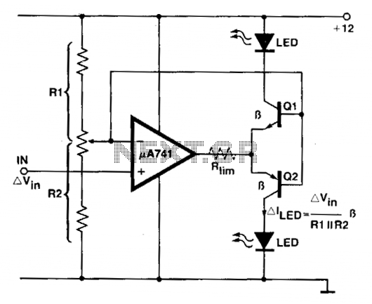
An operational amplifier (op amp) is utilized as a comparator and as a current sink for an LED. The output voltage of the amplifier varies by approximately 1.4 V based on the direction of the current. At any given...

The core component of this digital volume controller (DVC) circuit is the IC2 4067, which is a 16-channel analog multiplexer. A 1kΩ resistor is connected between each input and output, allowing the multiplexer to function similarly to a potentiometer....
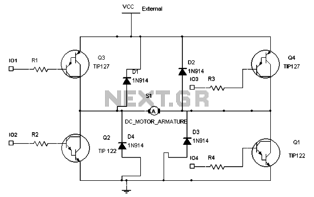
To maintain a constant speed of the motor under varying load conditions, a control application circuit is required. An H-Bridge circuit can be utilized to manage both the speed and direction of the motor. The accompanying diagram illustrates the...
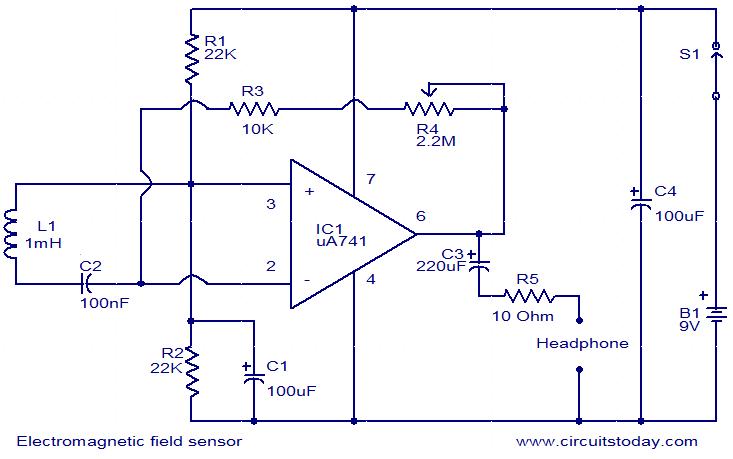
The following circuit illustrates an Electromagnetic Field Sensor Circuit Diagram. This circuit is based on the uA741 integrated circuit. Features: it is used to sense electromagnetic fields. The Electromagnetic Field Sensor Circuit utilizes the uA741 operational amplifier to detect variations...
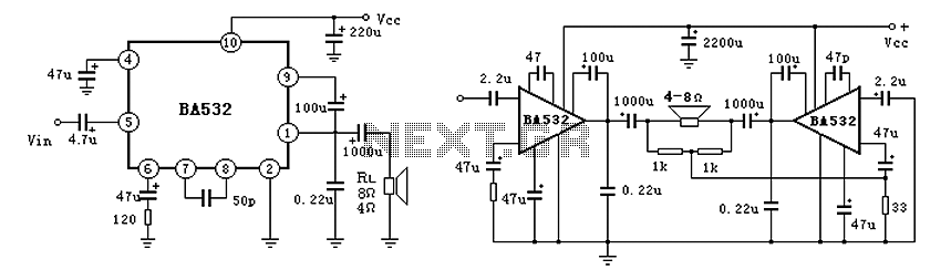
BA532 is a low-frequency power amplifier circuit designed for an output transformerless (OTL) application, capable of delivering up to 5.8W of output power. It features built-in protection against load short-circuits, over-voltage, and over-temperature conditions. The amplifier is housed in...
Operating at approximately 1.1 GHz, the detector senses disturbances in the electromagnetic field surrounding the antenna. The Doppler signal generated by detector D1 is amplified and used to control a power MOSFET switch. The antenna consists of a short...