
250mW audio amplifier

The three-transistor audio amplifier circuit is designed to enhance audio signals for various applications, particularly in compact electronic devices. The circuit employs a configuration where the BC547 transistor (Q1) acts as a preamplifier, boosting the weak audio signals received from the audio source. The output stage consists of complementary transistors BC337 (Q3) and BC227 (Q2), which are configured to drive an 8-ohm speaker effectively, delivering a power output of 250 mW.
The use of a potentiometer (R5) allows for adjustable volume control, enabling users to fine-tune the audio output to their preference. Capacitor C1 plays a crucial role in filtering out any DC offset from the audio input, ensuring that only the desired audio signal is amplified. This is essential for maintaining audio fidelity and preventing distortion.
Resistor R2 contributes to the overall stability of the amplifier circuit, which is vital for consistent performance and reliability. The design is particularly advantageous for small radio sets, where space is limited, yet high-quality audio output is desired. Additionally, this amplifier can serve as an effective preamplifier stage in larger, high-power audio amplifiers, enhancing the versatility of the circuit in various audio applications.Here is a very simple three transistor audio amplifier circuit that can deliver 250mW to a 8Ohm speaker. Complementary transistors BC337 and BC227 (Q3 and Q2) are used as the output pair. Transistor Q1 (BC 547) acts as the preamplifier. POT R5 can be used as a volume control. Capacitor C1 decouples the DC from the audio source. Resistor R2 ensures better stability for the amplifier. This amplifier is very suitable for application in small radio sets and as a preamplifier in high power audio amplifiers. 🔗 External reference
Related Circuits

This design utilizes a well-established circuit topology for the power amplifier, employing a single-rail supply of approximately 60V and capacitor coupling for the speaker(s). The benefits for a guitar amplifier include simple circuitry, even with relatively high power outputs,...
This is a 300 W RF amplifier designed for FM transmission, capable of operating within the frequency range of 88 to 108 MHz. The amplifier utilizes two TP9383 transistors, enabling it to deliver up to 300 W of output...
The audio ground is completely isolated from the digital ground. The top copper layer is utilized as a shield for both the audio and digital ground, which aids in preventing the audio section from picking up noise from the...
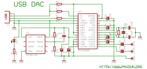
There is a significant interest in audio DAC design, particularly in creating a low-cost yet powerful audio DAC. This guide will provide instructions on how to build a personal audio DAC using the PCM2902 circuit. The project involves designing...
A 2-meter 144MHz push-pull amplifier capable of generating 200W, utilizing two DV28120T transistors. The 2-meter 144MHz push-pull amplifier is designed for high-power applications, particularly in amateur radio and communication systems. The amplifier operates within the 144MHz frequency range, making it...
Here is a simple little HF TX. It may be modified for all the HF bands, but the details given are only for the 7MHz band. The basic transmitter uses two transistors; BC547 (as usual) and will deliver over...