
256 Run Light (8bit Bin Up-Down)
")
The circuit utilizes an 8-bit up/down counter, which is capable of counting both upwards and downwards based on the control signals provided. The primary function of the counter is to maintain a count that can be displayed or utilized for various applications, such as timing or sequencing in digital systems. The counter receives input signals that dictate whether it should increment or decrement its count.
Complementing the counter is an 8-bit binary to 256 decimal decoder. This decoder takes the binary output from the counter and converts it into a one-hot encoded signal that represents one of the 256 possible states. Each output of the decoder corresponds to a unique count value from the counter, allowing for straightforward interpretation of the counter's state.
The integration of these two components results in a run light system, where the current count can be visually represented through LEDs or other indicators. As the counter increments or decrements, the corresponding output from the decoder activates the appropriate light, providing a clear visual indication of the current count status.
In practical applications, this circuit can be employed in various digital devices requiring counting functions, such as timers, event counters, or even in gaming systems where score tracking is essential. The design is efficient, leveraging the simplicity of binary counting with the versatility of a decoder to provide a user-friendly output. Proper power supply considerations and signal integrity must be maintained to ensure reliable operation of the counter and decoder in the intended application.This is A 8 bit Up/Down Counter that together with the “8 Bit Binary to 256 Decimal (1 of 256) Decoder “ makes a Run Light. I tried to to put all the 256.. 🔗 External reference
Related Circuits
Automatic color holiday lights circuit The automatic color holiday lights circuit is designed to control the operation of decorative lights during festive seasons. This circuit typically utilizes a microcontroller or a timer to manage the sequencing and color changes...
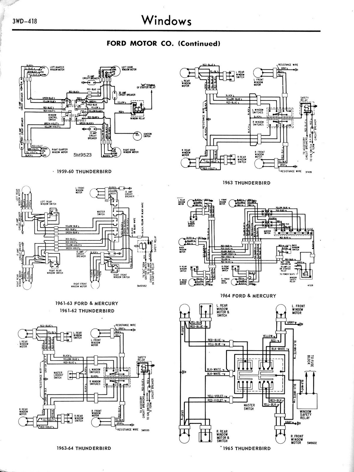
Toyota MR2 Exterior Lights Wiring Diagram Manual PDF Download. The Toyota MR2 Exterior Lights Wiring Diagram Manual provides a comprehensive guide for understanding the wiring configurations associated with the exterior lighting system of the Toyota MR2 model. This manual is...
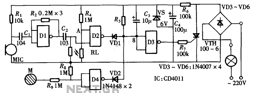
The circuit integrates sound and light control with touch functionality, creating a fully operational delay section light switch circuit. It consists of light control, voice circuits, and a touch control circuit, all triggered by a thyristor switch. The described circuit...
Electronics tutorial about light sensors including photocells, LDR, photodiodes, phototransistors, photovoltaic cells, and light-dependent resistors. Light sensors are crucial components in various electronic applications, enabling devices to respond to changes in ambient light levels. This tutorial covers several types of...
The BC547 transistor has a maximum operating current of 100 mA and a maximum voltage rating of 65 volts. When oriented with the label facing the viewer, the three terminals from left to right are collector, base, and emitter....
Typically, when a car door is closed, the dome light turns off immediately. This circuit allows the dome light to gradually fade in brightness before eventually turning off. An electronic transformer dims halogen lamps and is a straightforward device...