
Sound and light control touch delay saving switch integrated circuit diagram

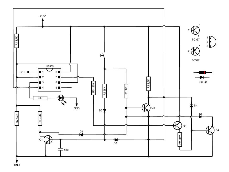
The described circuit serves as a multifunctional delay light switch, effectively combining three distinct control mechanisms: light sensing, sound activation, and touch input. The core component of this system is a thyristor switch, which acts as the primary trigger for the circuit's operation.
The light control circuit is designed to detect ambient light levels. When the light falls below a predetermined threshold, the circuit activates the thyristor, allowing current to flow and illuminating the connected light source. This function is particularly useful for automatic lighting in dark environments.
The voice control circuit utilizes a microphone and signal processing components to detect specific sound patterns or commands, which also trigger the thyristor. This feature allows users to control the lighting through vocal commands, enhancing convenience and accessibility.
The touch control circuit incorporates a touch-sensitive interface that enables users to manually activate or deactivate the light by simply touching the designated area. This feature provides a direct and intuitive method of control, complementing the automated functions of the light and voice circuits.
Overall, the integration of these three functionalities into a single circuit not only enhances the user experience but also promotes energy efficiency by ensuring that the light is only activated when necessary. The use of a thyristor switch ensures reliable operation and quick response times, making the circuit suitable for various applications, including home automation systems and smart lighting solutions. As shown in the circuit with a set of sound and light control touch three functions into one to form a fully functional delay section light switch circuit as shown in FIG. Part of the circuit, light control circuit, voice circuits and touch control circuit is triggered by a thyristor switch.
Related Circuits
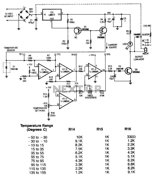
The LM35 temperature sensor outputs 10 mV/C for each degree Celsius above 0°C. At 20°C, the output voltage is calculated as 20 × 10 = 200 mV. The circuit consumes minimal power. Additionally, the load resistance should not be...
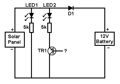
A small solar panel is used to maintain a 12V car battery. The panel provides approximately 75mA of current to the battery under full sunlight conditions. The described circuit employs a solar panel specifically designed for battery maintenance applications. The...
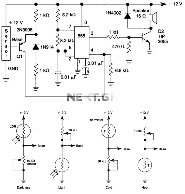
The tone generated by a 555 oscillator can be activated by heat or light, which causes Q1 to conduct transistor Q2 (TIP 3055). Q2 (TIP 3055) functions as an audio amplifier and speaker driver. The circuit utilizes a 555 timer...
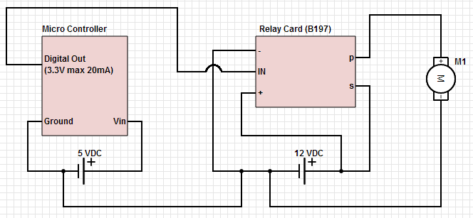
The objective is to control a 12 VDC device (on/off) from a microcontroller using a relay card. The relay requires a 12 VDC operating power supply. To achieve the control of a 12 VDC device using a microcontroller and a...
This circuit, based on the NE555 timer, activates and deactivates the IC output using a momentary switch. It functions similarly to a mechanical latching relay, but resets to its initial state when the power supply is turned off. This...
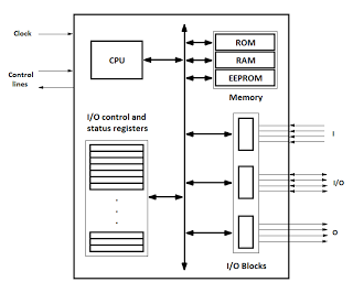
Microcontrollers are integrated circuits that consist of a microprocessor along with additional units such as memory and input/output peripherals. This implementation allows for savings in time, space, and cost. Microcontrollers are commonly abbreviated as MCU (Microcontroller Unit), µC, or...