
Arduino Running A DC Motor and High Current Lamp

The BC547 transistor is a widely used NPN bipolar junction transistor (BJT) that is suitable for low-power amplification and switching applications. Its configuration allows it to operate effectively in various electronic circuits. The collector, base, and emitter terminals serve distinct functions: the collector receives the input current, the base controls the transistor's operation, and the emitter outputs the amplified current. While the BC547 can handle up to 100 mA, care must be taken not to exceed this limit, as illustrated by the experience of damaging a transistor during setup due to incorrect current levels.
Conversely, the IRF520 is an N-channel MOSFET that is utilized for higher power applications. Its gate, drain, and source terminals allow for efficient switching and amplification of electrical signals. The IRF520 can manage a maximum voltage of 100 volts and a current of up to 9.7 amperes, making it suitable for driving larger loads, such as motors or high-power LED arrays. The gate terminal is particularly critical, as it requires a voltage to turn the MOSFET on, allowing current to flow from the drain to the source.
In summary, both transistors serve essential roles in electronic circuits, with the BC547 being ideal for low-power applications and the IRF520 for higher power needs. Proper attention to the specifications and limitations of each component is crucial for successful circuit design and implementation.BC547 transistor. Max operating current is 100 mA while max voltage is 65 volts. With the transistorlabelfacing the reader, the three legs from left to right are collector, base and emitter. Note: I destroyed one BC547 transistor while setting this up. I tested the dc motor I used using digital multimeter, it wasgettingmax of 150 mA. An obvious mi stake. The IRF520 Transistor. Facing the label to reader, the three pins from left to right are gate, drain and source. Max voltage is 100 volts while max current is 9. 7amperes. 🔗 External reference
Related Circuits
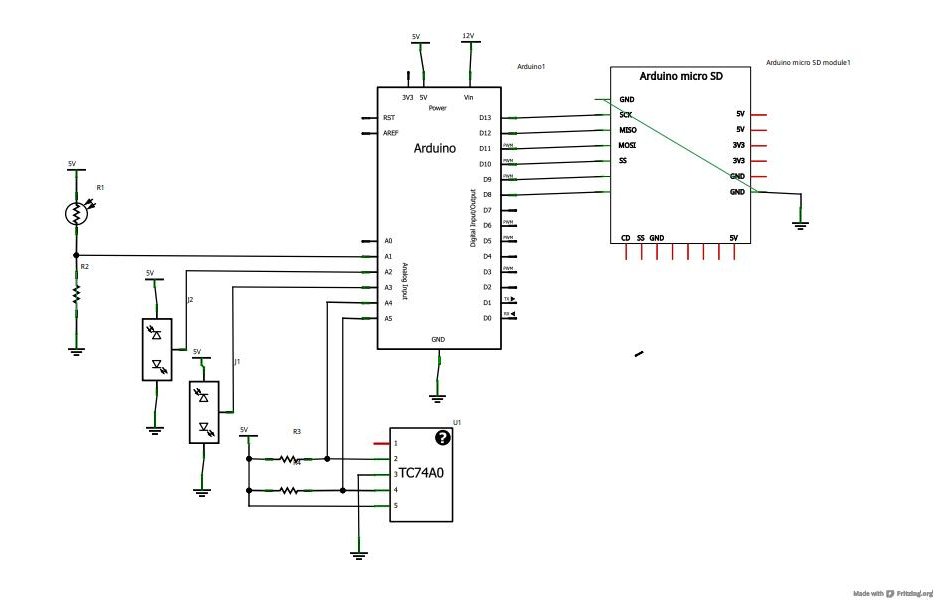
Now that the basics have been covered in tutorials 1-10, it is time to pursue more complex projects. In this episode, an SD card shield from cooking-hacks.com will be utilized to create a data logger. The process of reading...
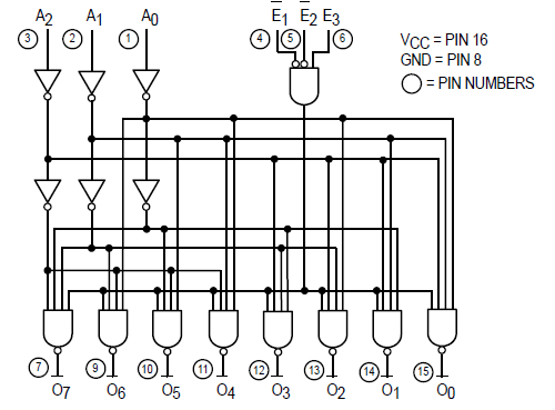
The Motorola SN54/74LS138 is recognized as a 1-of-8 decoder or demultiplexer, specifically engineered for high-speed bar memory chip select address decoding. The accompanying diagram illustrates the logic configuration of the SN54/74LS138 demultiplexer. According to the SN54 datasheet, the multiple...

The SN754410 Dual Motor Control circuit is illustrated below. It is straightforward in design, with the PIC serving as the central processor. The main components included in the schematic are the 7805 voltage regulator, the 18F452 microcontroller, and the...
The circuit illustrates a method to obtain a voltage of 90V from a 1.5V battery supply. The LT1073 switching regulator from Linear Technology operates in boost mode and can function with an input voltage as low as 1.0V. The...
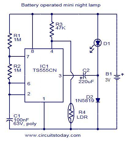
This circuit is designed as a low-power LED night lamp that automatically switches off during daytime. The CMOS timer IC TS555CN is configured as a square wave generator operating at approximately 5 Hz. The output voltage from the IC...
This circuit is designed to demonstrate high-frequency high voltage, capable of producing voltages up to approximately 30 kV, depending on the transformer used. It is economical and straightforward to construct, primarily utilizing a standard TV flyback transformer. The circuit...