
256 Run LIght (for the 8bit bin to 256 / 1 of 256)
")
The circuit utilizes a switch (S1) to control the direction of operation, allowing for two modes: upward and downward movement. This switch is typically a double-pole double-throw (DPDT) type, which can effectively reverse the polarity of the output signal depending on its position.
The potentiometer (Pot1) is employed to vary the clock speed, which can be crucial for applications requiring precise timing adjustments. This component is generally a linear or logarithmic potentiometer, providing a variable resistance that modifies the frequency of the clock signal fed into the circuit. The clock signal can be generated using an oscillator circuit, where the frequency is determined by the resistance set by Pot1 and any associated capacitive components.
LED D1 functions as a visual indicator of the clock speed. It typically connects in parallel with the clock output, allowing it to illuminate in accordance with the frequency of the clock pulses. The brightness of the LED can vary depending on the clock speed; higher speeds may result in a more intense light, while lower speeds may dim the LED.
Overall, this circuit configuration is beneficial for applications such as motor control, where direction and speed adjustments are essential. The integration of the switch, potentiometer, and LED provides a user-friendly interface for real-time adjustments and visual feedback on the operational status of the circuit.With Switch S1 you can change direction (Up/Down), Pot1 is for the clock speed and the Led D1 is only an indicator for the clock speed. .. 🔗 External reference
Related Circuits
It allows car headlights to flash on and off simultaneously or alternately. Components: 555 IC, transistor, resistor, relay, polarized capacitor. The circuit utilizes a 555 integrated circuit (IC) in a monostable or astable configuration to control the flashing of car...

This example demonstrates a robust design featuring novelty lights that flash in a specific sequence, utilizing a 1-3-2-4 vault chase mode. The circuit includes diodes VD1 to VD4, which form a bridge rectifier, converting AC voltage to a full-wave...
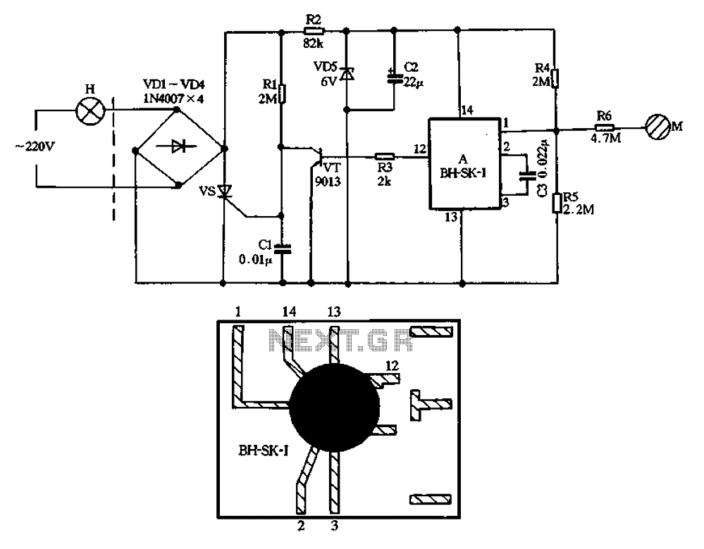
The BH-SK-I is a touch light switch circuit that integrates a single bond voice integrated circuit. The circuit is divided into two sections: the left section represents the general lighting lines, while the right section illustrates the touch switch....
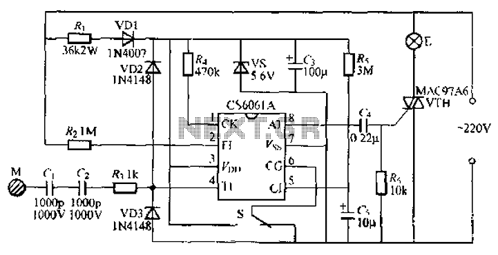
The CS6061A integrated circuit is designed for touch-step dimming lights. It features a two-state female switching function and is reliable, capable of adapting to long cables and larger touch-sensitive pad loads (400pF). The collector circuit of the CS6061A utilizes...
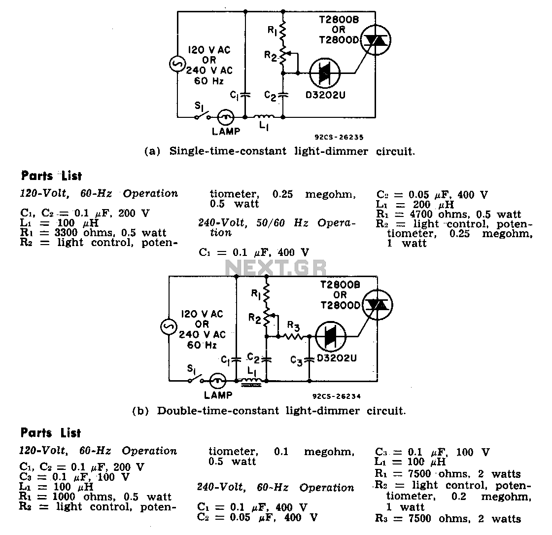
The two lamp-dimmer circuits differ in that one employs a single-time-constant trigger network, while the other uses a double-time-constant trigger circuit. This second configuration reduces hysteresis effects and extends the effective range of the light-control potentiometer. Hysteresis refers to...
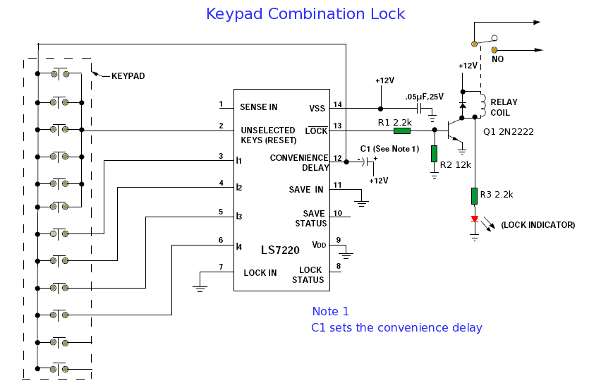
When connected to a ten-digit keypad, the circuit can identify one four-digit combination from a total of 5040 possible codes. Upon entering the correct four-digit sequence from the keypad, the LOCK feature activates while the Lock Status deactivates. The...