
555 Timer For Headlight Flasher

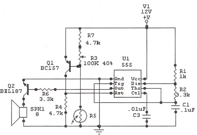
The circuit utilizes a 555 integrated circuit (IC) in a monostable or astable configuration to control the flashing of car headlights. In a typical application, the 555 IC is configured to produce a square wave output that alternates the state of the headlights. This output can be used to drive a transistor, which acts as a switch to control a relay. The relay, in turn, is responsible for managing the higher current required by the car's headlights.
The circuit begins with the 555 IC, which is powered by the vehicle's electrical system, typically 12V. The timing components, including resistors and a polarized capacitor, are connected to the 555 IC to set the frequency and duration of the flashing. The resistor values and the capacitance of the capacitor determine the rate of flashing, allowing for customization based on user preference.
When the 555 IC is triggered, it sends a pulse to the base of the transistor. The transistor, functioning as a low-side switch, allows current to flow through the relay coil, energizing it. This action closes the relay contacts, turning on the headlights. The headlights will remain on for the duration set by the timing components before the 555 IC resets and turns them off. If the circuit is configured for alternating flash, a second 555 IC or additional components may be employed to create a staggered effect.
In summary, this circuit effectively provides a visual alert through the vehicle's headlights by utilizing a 555 IC for timing, a transistor for switching, and a relay to handle the load of the headlights, all while allowing for simultaneous or alternating flashing patterns based on the configuration of the components used.It allow your car headlights to flash on and off at the same time or it will cause them to flash alternately. Component: 555IC, Transistor, Resistor, Relay, Polarised Capacitor. 🔗 External reference
Related Circuits
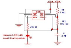
The IC 555 Light Alarm (Sun Up Alarm) is a circuit designed to emit a loud alarm at dawn, particularly beneficial for individuals who struggle to wake up even with a traditional alarm clock. The circuit can be modified. The...
After one cycle of operation, SCR1 will be activated, resulting in a low voltage being applied to the UJT emitter circuit, which interrupts the tuning function. When pushbutton SI is pressed, or a positive pulse is applied at point...
A low power H-bridge may be necessary for driving a motor. The 555 integrated circuit (IC) can handle a load of up to 200 mA, either sourcing or sinking, making it a potential driver if the output can be...
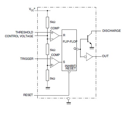
This article offers valuable information for creating a specific oscillator or pulse generator using integrated circuits (ICs), resistors, and capacitors, regardless of the version of the 555 IC utilized. The 555 timer IC is a versatile component widely used in...
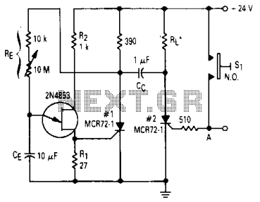
When the lights of an oncoming car are detected by the photo-transistor Q1, the circuit activates. Sensitivity is adjusted by the 22-megohm resistor, R5, to approximately half a foot-candle. The relay employed has a 12-volt, 0.3A coil. The L14C1...
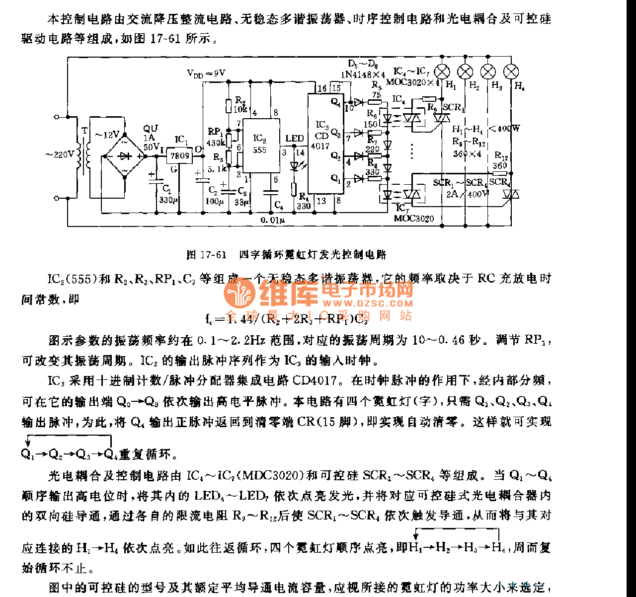
This control circuit consists of an AC step-down rectifier circuit, an astable multivibrator, a timing control circuit, an optocoupler circuit, and an SCR driving circuit, as illustrated in Figure 17-61. The astable multivibrator is formed using IC2 (555), resistors...