
25W Low Power Inverter

The 555 timer is a versatile integrated circuit commonly used in various applications, including oscillators, timers, and flip-flops. In this specific configuration, the 555 timer operates as an astable multivibrator, generating a continuous square wave output. The frequency of oscillation is primarily determined by the resistors R2 and R1, along with capacitor C1, which sets the charge and discharge time of the timing capacitor. The output from pin 5 can be used to drive further circuitry or as a control signal.
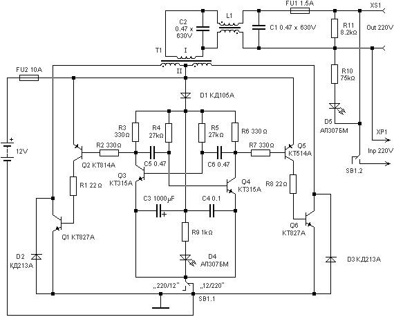
The phase inverter section of the circuit utilizes transistors Q1 and Q2 to create a push-pull output, which is essential for driving the transformer effectively. This configuration ensures that when one transistor is conducting, the other is turned off, providing efficient energy transfer to the transformer. The use of a center-tapped transformer allows for both stepping up the voltage and providing a balanced output for various applications.
The inverter's design emphasizes stability and efficiency, operating within a low voltage range while providing sufficient output for small electronic devices. The separate oscillator design allows for flexibility in tuning the frequency, accommodating a range of applications from low-frequency signals to higher frequencies as needed.
In addition, the automatic switching emergency light circuit demonstrates practical applications of the inverter, providing essential functionality during power outages. The inclusion of overcharge protection in the battery charger circuit enhances the safety and longevity of the battery used in conjunction with the inverter.
Overall, this inverter circuit exemplifies a practical solution for powering low-wattage devices from a DC source, with a focus on efficiency, stability, and ease of use. The detailed design considerations, including component selection and configuration, contribute to the inverter's reliability and effectiveness in various scenarios.The first section of the 555 timer is wires as an astable oscillator with R2 and C1 setting the frequency. The output is available at pin 5. The second section is wired as a phase inverter. That output is available at pin 9. Resistor R3 and R4 keep output transistor Q1 and Q2 from loading down the oscillator. The two transistors drive the transfor mer push-pull fashion. When one transistor is biased-on, the other is cut-off. The transformer is a 120V/18V center tapped that is connected backwards, so that is steps the voltage up rather than down. Oscillator circuit U1, R1, R2 and C1 operates from about 4 to 6V with very stable output. Tags: 25w inverter, 25w power inverter, 6v inverter circuit, inverter circuit diagram, low power inverter, low power inverter circuit, power inverter circuit diagram, This inverter circuit can be used to power electric razors, stroboscopes and flash tubes, and small fluorescent lamps from a 12 volt car battery.
In contrast to the usual feedback oscillator type of inverter, the oscillator of this inverter is separate from the output stage, which allows easy adjustment of the oscillator frequency to suit. The following diagram is the schematic of simple easily tuned / adjustable sine and square wave oscillator.
This circuit provides sine and square wave at frequency of below 20Hz up to above 20KHz. The benefit of this circuit diagram is that you can adjust the output frequencyby varry the variable resistor of R6. The schematic diagram shown right here is the automatic switching-on emergency light circuit which is controlled using IC.
The most important capabilities of this circuit are: automatic switching-on of the light on main power failure and battery charger with overcharge protection. When mains electrical power is absent, relay RL2 is in deenergised state, feeding DC. This is low cost fully transistorised inverter circuit capable of driving medium loads of the order of 40 to 60 watts using battery of 12V, 15 Ah or higher capacity.
Transistors T1 and T2 (BC548) form a 50Hz multivibrator. For obtaining correct frequency, the values of resistors R3 and R4 may have to be changed. Here the project report of DC/AC pure sine wave inverter. This report focuses on DC to AC electrical power inverters, which aim to efficiently transform a DC power source to a high voltage AC supply, just like electrical power that would be presented at an electrical wall outlet. Inverters are utilised for a lot of. 🔗 External reference
Related Circuits
The circuit is designed to create a power amplifier that utilizes E80CC and EL34 vacuum tubes to achieve optimal performance, providing an output of 35 Watts. The power amplifier circuit employs E80CC and EL34 vacuum tubes, which are known for...
220 watts Uninterruptible Power Supply. Refer to the designated page for an explanation of the related circuit diagram for this power supply. The 220 watts Uninterruptible Power Supply (UPS) is designed to provide reliable backup power during outages, ensuring that...
This circuit was designed and manufactured in the 1980s and has functioned without issues since then. It does not present any particular constructional problem, beyond the known: the attention in the provided force of power supply, choice of suitable...

This is a linear amplifier that requires advanced knowledge in electronics due to the complexity of the schematic diagram for a handmade circuit. It is advisable to redesign the schematic diagram using circuit design software such as DipTrace, Eagle,...
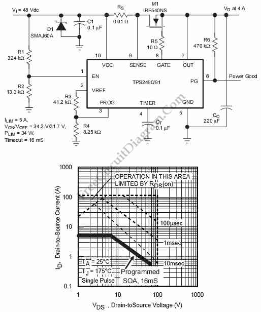
This is a positive high-voltage hot swap controller circuit with a power limiter. This circuit utilizes the TPS2491 or TPS2490, as both of them have specific features. The positive high-voltage hot swap controller circuit is designed to safely connect and...

Below 10 MHz, the development of engineering models is relatively straightforward and not significantly influenced by printed circuit board layout. In the VHF range, parasitic circuit elements and unwanted coupling can severely impact efforts to achieve cost-effective performance without...