
2Mhz Frequency Counter Circuit

The 2-MHz frequency counter circuit is designed to accurately measure and display frequency signals up to 2 MHz. The core of the design is the ICM7224IPL, which integrates both the counter functionality and the display driver, facilitating a streamlined architecture that reduces component count and complexity. The LCD-004 display is utilized for visual output, allowing users to easily read the frequency measurements.
The signal amplification stage is critical for ensuring the input signal is adequately processed. Transistors Q2 and Q3 are configured as a differential amplifier to enhance the input signal's amplitude, improving the overall sensitivity of the frequency counter. This is particularly important in applications where the input signal may be weak or subject to noise.
The crystal oscillator, consisting of U3-c and XTAL1, serves as the timing backbone of the circuit. It generates a stable frequency reference that is essential for accurate counting. The crystal's frequency stability ensures that the measurements taken by the counter are precise and reliable. The oscillator output is then divided by two stages, creating multiple timing references. This feature allows for flexibility in measurement, as users can select among three different timing references according to their specific requirements.
The logic chips incorporated into the circuit are responsible for managing the timing pulse circuitry, coordinating the operation of the counter, and ensuring that the display driver receives the correct signals to present the frequency reading. The design emphasizes modularity, enabling easy upgrades or modifications to accommodate future enhancements or changes in application needs.
Overall, this frequency counter schematic represents a well-thought-out design that combines essential components to achieve accurate frequency measurement and display, making it suitable for a variety of electronic applications. This is a schematic and block diagram of a 2-MHz frequency counter. It uses and LSI counter/display driver, LCD readout, and a few logic chips for timebase and timing pulse circuitry. Q2 and Q3 form a signal (input) amplifier. The circuit contains a crystal oscillator built around U3- c and XTAL1, which provides the primary timing-reference signal.
That signal is then divided twice to provide two additional timing references, giving the circuitry three selectable timing references. The ICM7224IPL is an integrated circuit that consists of the counter and display driver to drive the LCD-004 display.
Related Circuits

Binu submitted a new resource: Circuit and Program to Interface MT8870 with AT89S51 (version 1.0) - Decoding the DTMF signals from the telephone line. The circuit designed to interface the MT8870 DTMF decoder with the AT89S51 microcontroller is aimed at...
The circuit was designed to create an electronic oscillator known as a Wien Bridge Oscillator, which can be used for the creation of low-frequency sine waves. The Wien Bridge Oscillator is a type of electronic oscillator that generates sine waves....
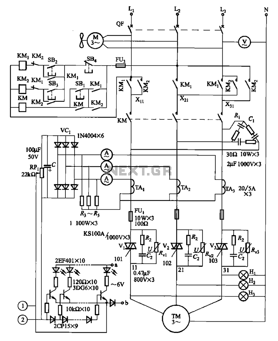
The circuit illustrated in Figure 3-178 is designed for controlling the speed and torque of a motor used in a continuous casting machine. It consists of the main circuit, a trigger circuit, and both manual and automatic control signal...
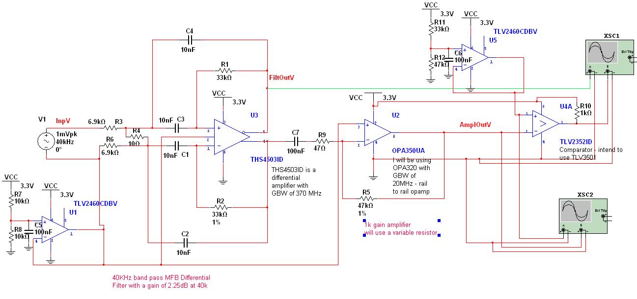
A circuit has been designed to detect the duration of an ultrasonic pulse as it travels a certain distance. The input signal is sourced from a 40 kHz ultrasonic receiver. The first stage consists of a 40 kHz band-pass...

The digital circuit that is particularly useful is the One-Shot circuit, also known as a monostable multivibrator circuit. This circuit exhibits a specific behavior where it generates a single output pulse in response to an input trigger. The One-Shot circuit,...
The following circuit illustrates a Power Amplifier Circuit Diagram utilizing a 2N3055 transistor. Features include a 500-ohm current and an optimal voltage of 50V. The power amplifier circuit based on the 2N3055 transistor is designed to deliver significant output power,...