
Power AmplifierCircuit With 2N3055 Transistor

The power amplifier circuit based on the 2N3055 transistor is designed to deliver significant output power, making it suitable for applications in audio amplification and other high-power scenarios. The 2N3055 is a widely used NPN power transistor known for its robustness and ability to handle high currents, typically up to 15A, and voltages of 60V.
In this circuit, the transistor is configured in a common emitter arrangement, which provides voltage gain and is commonly employed in amplifier designs. The input signal is fed into the base of the transistor through a coupling capacitor, which blocks any DC offset and allows only the AC component of the signal to pass through. The biasing resistors are crucial as they set the operating point of the transistor, ensuring it remains in the active region for linear amplification.
The output stage of the circuit typically includes a load resistor connected to the collector of the 2N3055, allowing the amplified signal to drive speakers or other devices. The emitter may have a resistor for stability and to provide feedback, which can help linearize the output and improve performance.
Power supply considerations are also essential; the circuit requires a well-regulated DC supply, capable of providing the necessary current and voltage levels, ideally around 50V for optimal performance. Proper heat sinking for the 2N3055 is critical, as it can generate significant heat during operation, which could lead to thermal runaway if not adequately managed.
Overall, this power amplifier circuit is a reliable solution for boosting audio signals, with the 2N3055 transistor providing a balance of performance and durability for various applications.The following circuit shows about Power Amplifier Circuit Diagram. This circuit using 2N3055 Transistor.Features: 500ohm current, 50V optimal .. 🔗 External reference
Related Circuits
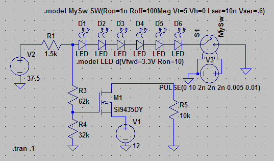
A suitable method to sense when some LEDs in a garage door opener are illuminated. A power source, potentially the same as Vout, connects to a 1.5 kΩ resistor, which then connects to six LEDs followed by a transistor....
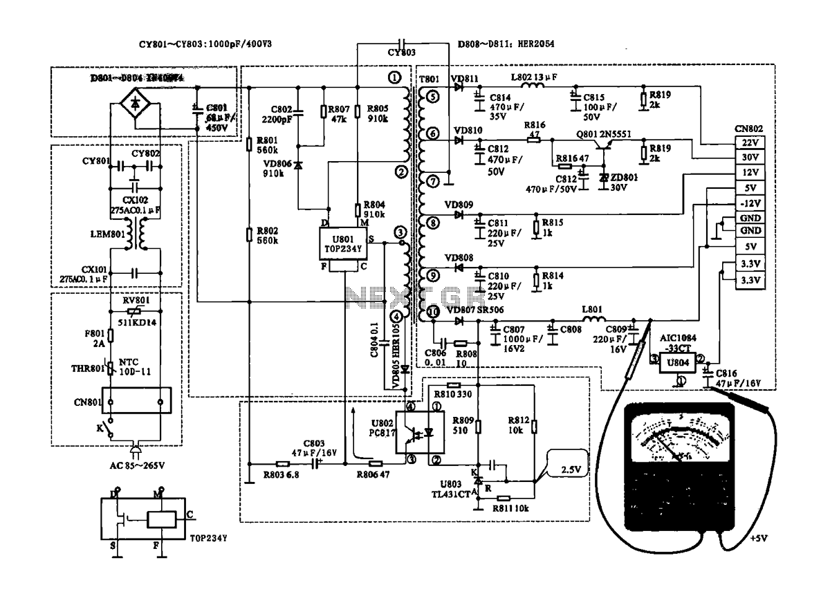
The Coship CDVB3188V receiver features a switching power supply circuit similar to the CDVB3188C model. The circuit includes several key components: an AC input circuit, an anti-jamming filter circuit, a complete flow filter circuit, and a switching oscillation circuit....
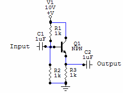
Two examples of the most common types of Voltage followers (buffers). You can find some theory behind them in our amplifier gain and buffer amplifier pages. This first circuit is a very simple one transistor voltage follower. Consists of...
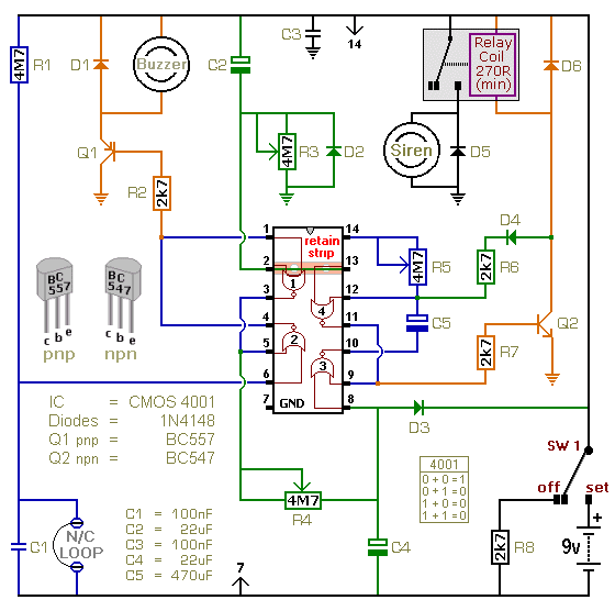
This is a single-zone alarm system featuring independently adjustable Exit, Entry, and Siren Cut-Off timers. It is designed to accommodate standard normally-closed input devices, such as magnetic reed contacts, foil tape, and passive infrared sensors (PIRs). The system can...
The circuit is designed to set a delay time based on the voltage Us and the resistor R. In this configuration, S1 acts as the discharge switch for capacitor C. When switch S1 is closed, the stored charge in...
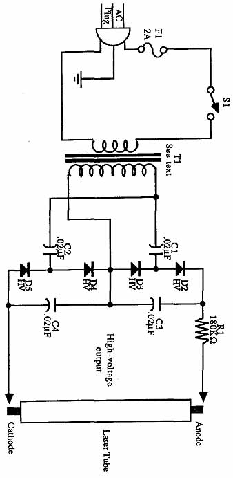
Construct universal power supplies, including low-voltage power supplies for operating electronic equipment. The designs include single- and dual-voltage regulated supplies, an all-purpose adjustable version, and battery pack regulators. A helium-neon laser tube requires a high-voltage power supply for operation....