
Simple microphone preamplifier

Additional Detailed Content: The microphone preamplifier circuit is designed to function as an intermediary device, amplifying the weak signal from the microphone before it reaches the stereo amplifier. The circuit is compatible with a range of inputs, including line, CD, aux, and tape, making it versatile enough to be used with most home stereo systems.
The preamplifier is designed to accept inputs from both dynamic and electret microphones, with the circuit providing the necessary power for the electret microphone elements. This feature expands the range of microphones that can be used with the preamplifier, increasing its utility.
The design philosophy behind this circuit is simplicity. The aim is to make it easy enough to be constructed even by those with a basic understanding of electronics. This was particularly important when the circuit was initially designed to function as an external microphone preamplifier for a mixer.
Although the performance of the circuit may not be superior to more complex designs, it is more than adequate for a range of applications that do not require high-end performance. This makes it a suitable choice for hobbyist projects or for those who are just starting out in electronics and wish to gain practical experience with building and using circuits.
In summary, this microphone preamplifier circuit is a versatile, easy-to-build solution that can be used with a variety of microphones and stereo systems. Its performance is adequate for many applications, making it a practical choice for a wide range of users.This is a simple microphone preamplifer circuit which you can use between your microphone and stereo amplifier. This circuit amplifier microphone suitable for use with normal home stereo amplifier line/CD/aux/tape inputs.
This mic preamp can take both dynamic and electret microphone inputs (preamplifer provides power foe electret microphone elements). The idea of this circuit is to keep the design as simple as possible to be easy to build. That was my goal when I needed a simple external microphone preamplifer for my mixer. The performance of the circuit is nothing superior but can be used with many not so serious projects.
🔗 External reference
Related Circuits
Simple Surround Sound Decoder. Introduction This surround-sound decoder is based on the Hafler principle, first discovered by David Hafler sometime in the early 1970s. The original idea. The simple surround sound decoder utilizes the Hafler principle to create an immersive...
The bi-directional sequencer employs a 4-bit binary up/down counter (CD4516) along with two "1 of 8 line decoders" (74HC138 or 74HCT138) to create the well-known "Night Rider" display. A Schmitt Trigger oscillator generates the clock signal for the counter,...
The circuit is a microphone amplifier for use with low impedance (~200 ohm) microphones. It will work with stabilized voltages between 6-30VDC. If you don`t build the impedance adapter part with T1, you get a micamp for higher impedance...
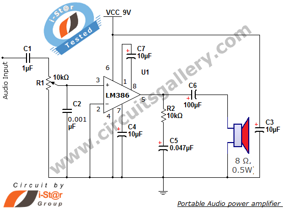
The i-St@r presents a simple mini audio amplifier circuit schematic utilizing the LM386 low voltage audio power amplifier IC. This circuit is designed to power medium-sized speakers from a music player that typically drives only earphones (LM386 headphone). The...
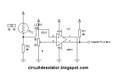
This is a common circuit block utilized in both digital and analog electronics. Its output depends on the relationship between its two input pins. One input is designated to provide the reference voltage, while the other is typically connected...
This circuit diagram represents a simple yet effective transmitter circuit, capable of transmitting telephone conversations. When the telephone receiver is on the hook, the line voltage is approximately 48 volts. The R7 preset resistor is adjusted to achieve a...