
2v to 25v 5a lm338 power supply circuit

The circuit design begins with the AC mains input, which is connected to a fuse (F1) that serves as a protective element, ensuring that excessive current does not damage the circuit. The fuse is rated for 8A, providing a safeguard against overcurrent conditions. Following the fuse, a varistor (V1) is integrated into the circuit to absorb voltage spikes, protecting sensitive components from transient surges.
The transformer (T1) plays a crucial role by stepping down the high voltage AC mains to a lower voltage of 24V AC. This reduction in voltage is necessary for safe operation of the subsequent components. The output from the transformer is directed to a bridge rectifier composed of four diodes (D1, D2, D3, D4). This configuration converts the AC voltage to pulsating DC voltage, which is essential for the operation of the LM338 regulator.
To stabilize the rectified DC voltage and reduce ripple, an electrolytic capacitor (E1) is connected in parallel with the output of the rectifier. This capacitor charges during the peaks of the rectified voltage and discharges during the troughs, effectively smoothing out the voltage fluctuations.
The LM338 adjustable voltage regulator is then connected to provide a stable output voltage adjustable between 2V and 25V. This regulator is capable of supplying up to 5A, making it suitable for various applications requiring different voltage levels. The output voltage can be set using external resistors connected to the adjust pin of the LM338, allowing for precise control over the output voltage.
Overall, this power supply design is versatile and can be adapted to different input voltage requirements by selecting appropriate components, ensuring reliability and performance in powering electronic devices.This project uses a LM338 adjustable 3 terminal regulator to supply a current of up to 5A over a variable output voltage of 2V to 25V DC. It will come in handy to power up many electronic circuits when you are assembling or building any electronic devices.
The schematic and parts list are designed for a power supply input of 240VAC. Change the rat ings of the components if 110VAC power supply input is required. As shown in the figure above, the mains input is applied to the circuit through fuse F1. The fuse will blow if a current greater than 8A is applied to the system. Varistor V1 is used to clamp down any surge of voltage from the mains to protect the components from breakdown. Transformer T1 is used to step down the incoming voltage to 24V AC where it is rectified by the four diodes D1, D2, D3 and D4.
Electrolytic capacitor E1 is used to smoothen the ripple of the rectified DC voltage. 🔗 External reference
Related Circuits
A simple FM transmitter connects a home entertainment system to a portable radio that can be moved around the house and into the backyard. For instance, music can be played from a CD player in the living room and...
This schematic represents a version of a simple LED chaser. A 555 timer is not utilized due to its high cost at local electronics stores, which is over $4 CAD. Instead, an oscillator is constructed using two sections of...
This design is for an interpolating scanner, a circuit featuring multiple signal inputs, a control voltage input, and a signal output. The output selectively transitions between inputs, smoothly fading from one to the next as the control voltage increases....
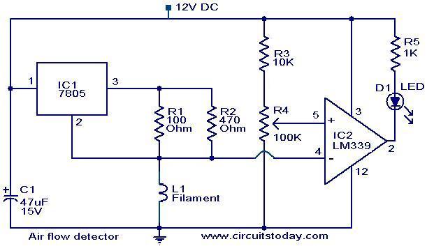
The filament of an incandescent bulb serves as the sensing component of the circuit. When there is no airflow, the resistance of the filament is low. In contrast, when airflow is present, the resistance decreases because the moving air...
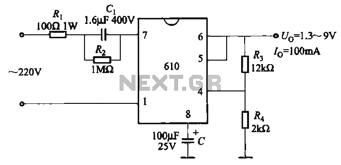
The output voltage can be calculated as follows: U = 1.3 (1 + R3 / R4) (V), where R3 and R4 are part of an adjustment potentiometer, allowing for a continuously adjustable output voltage. The described circuit involves a voltage...
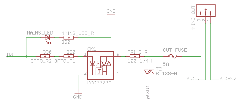
The heatsink on the triac is somewhat unclear. A maximum value of 10°C/W has been calculated, which raises concerns. The calculation is as follows: (maximum temperature - room temperature) / (maximum on-stage voltage * (milliamps / voltage) - junction-to-base...