
Adjustable output voltage power supply circuit MAX610

The described circuit involves a voltage output that is dependent on the resistors R3 and R4, which form a voltage divider configuration in conjunction with a potentiometer. The formula indicates that the output voltage (U) is 1.3 times the sum of 1 and the ratio of R3 to R4. This implies that by varying the resistance values of R3 and R4, the output voltage can be finely tuned to meet specific requirements.
In practical applications, the potentiometer serves as a means to adjust the resistance values dynamically. When R3 is increased relative to R4, the output voltage increases, whereas decreasing R3 or increasing R4 will lower the output voltage. This circuit can be utilized in various applications where precise voltage control is necessary, such as in power supplies, signal conditioning, or sensor interfaces.
The stability of the output voltage can be influenced by the tolerance of the resistors used, as well as the quality of the potentiometer. It is essential to select components that can withstand the operational conditions to ensure reliable performance. Additionally, the circuit may include filtering capacitors to stabilize the output and minimize voltage ripple, particularly in applications that require smooth and consistent voltage levels. Proper layout and grounding techniques should also be employed to reduce noise and interference in the circuit.The output voltage can be calculated as follows: U. . = 1. 3 (1 + R3 / R4) (V) adjustment potentiometer , continuously adjustable output voltage.
Related Circuits
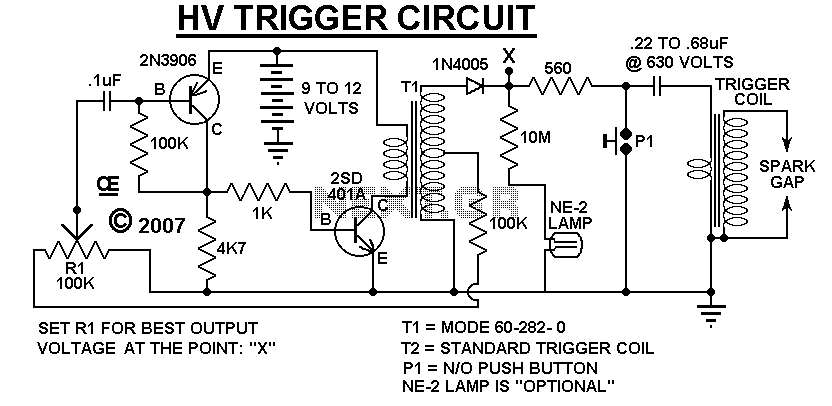
A Very Low Current, High Voltage Spark, that is Manually Triggered. Although its not easily Measured, the Peak Output voltage will be over 5,000 Volts. T1 is a small audio transformer and it steps up the voltage to about...
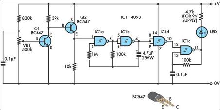
This design integrates power-on and low-battery indications, capable of operating with any battery voltage up to 15V. It features a very low current drain of 2mA or less and costs less than $3.50 with new components. When the battery...
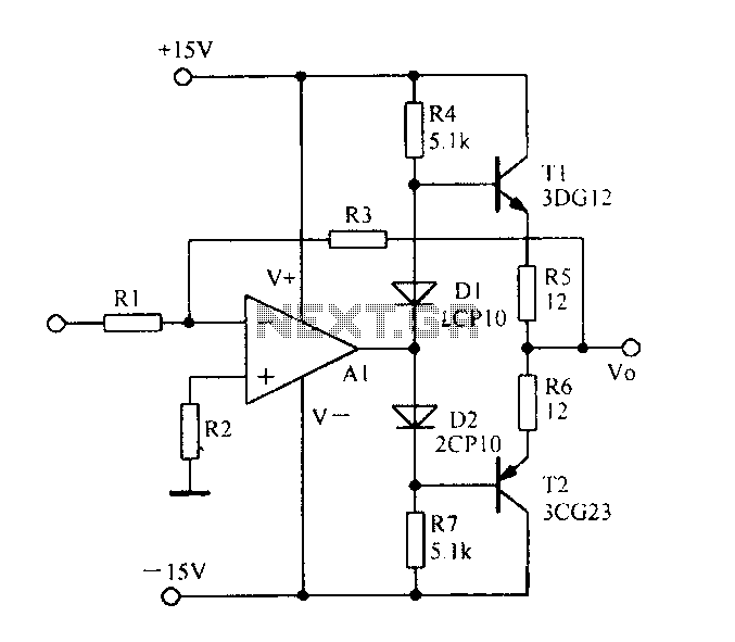
Current spreading bipolar output when the circuit diagram is as follows. The circuit described involves a current spreading bipolar output configuration. This type of circuit is typically used in applications requiring efficient current distribution across multiple output paths, often seen...
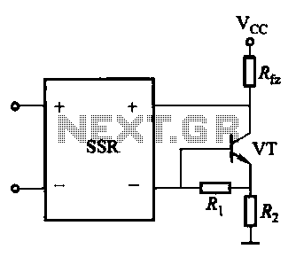
A DC solid-state relay (DC-SSR) driving a high-power load circuit is illustrated in (a) below; the high-power load driving circuit is depicted in (b) below. The DC solid-state relay (DC-SSR) serves as a crucial component in controlling high-power loads, providing...
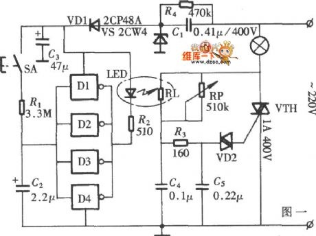
The diagram illustrates a lamp dimmer that gradually increases and decreases light intensity. This feature prevents sudden illumination, which can be a shock to the human eye, and also minimizes damage caused by inrush current when the lamp is...
This homemade metal detector circuit will assist in locating objects made of materials with relatively high magnetic permeability. It is not suitable for detecting certain metals. This metal detector circuit operates on the principle of electromagnetic induction, utilizing a coil...