
2W RF Amplifier with MOSFET LF2810A circuit diagram

The microstrip single-stage RF amplifier is designed to operate in radio frequency applications, where efficiency and gain are critical. The choice of the M/A-Com LF2810A MOSFET is significant due to its ability to handle high power levels while maintaining linearity and low distortion. Operating at a supply voltage of 12 VDC allows for a balance between power efficiency and performance, making it suitable for various RF applications.
Input and output matching is essential in RF circuits to maximize power transfer and minimize reflections. The use of trimmer capacitors allows for fine-tuning of the matching network, accommodating variations in component values and ensuring optimal performance across the desired frequency range. The trimpot for adjusting the gate bias voltage plays a crucial role in controlling the amplifier's output power, providing flexibility for different operational requirements.
The circuit board layout, as depicted in Figure B, is critical for the performance of the amplifier. The choice of 0.030-inch Duroid material is ideal for RF applications due to its low dielectric loss and stable electrical properties over a wide frequency range. The compression soldering of the circuit board onto the copper heat spreader enhances thermal management, ensuring that the MOSFET operates within safe temperature limits, thereby prolonging its lifespan and maintaining reliability.
The precision milling and drilling of both the circuit board and the heat spreader are vital for accurate alignment and secure mounting of the flange-mount transistor. This attention to detail in the mechanical design contributes to the overall performance and stability of the RF amplifier, making it a robust solution for high-frequency applications.Figure A is the schematic of the microstrip single stage RF amplifier. The amplifier is based on the M/A-Com LF2810A MOSFET. The transistor is actually a 10 watt, 28 volt part, but provides adequate gain for this application at 12 VDC. The amplifier provides greater than 40% efficiency at the desired output power. Trimmer capacitors are used for i nput and output matching. Output power is adjusted by a trimpot which sets the gate bias voltage. Figure B is the layout for the microstrip circuit board. The board material is 0. 030 inch Duroid. The circuit board is compression soldered onto a similarly sized copper heat spreader. The board and spreader are milled and drilled to accept the flange-mount transistor. 🔗 External reference
Related Circuits
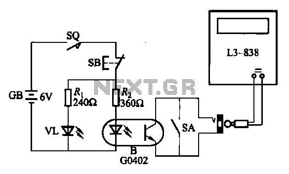
An electronic calculator features an automatic counting interface circuit, as illustrated in the accompanying figures. Figure (a) depicts a stroke switch controlled via optocoupler B. Figure (b) shows the application of a reed switch (KR) for pulse control signals....
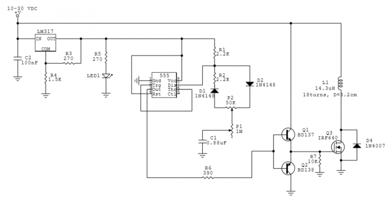
This circuit utilizes a 555 Integrated Circuit (IC) to generate a pulsed magnetic field, which can be employed for pulsed electromagnetic field (PEMF) therapy. The human body is affected by natural magnetic fields, including the Earth's magnetic field, geomagnetic...
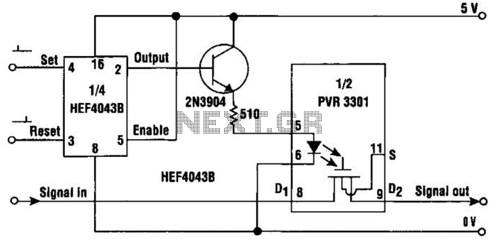
This simple circuit provides a solid-state equivalent of the electromechanical latching relay. The switching mechanism is clean, highly resistant to vibration and shock, and is not sensitive to magnetic fields or position. The circuit operates as follows: a set...
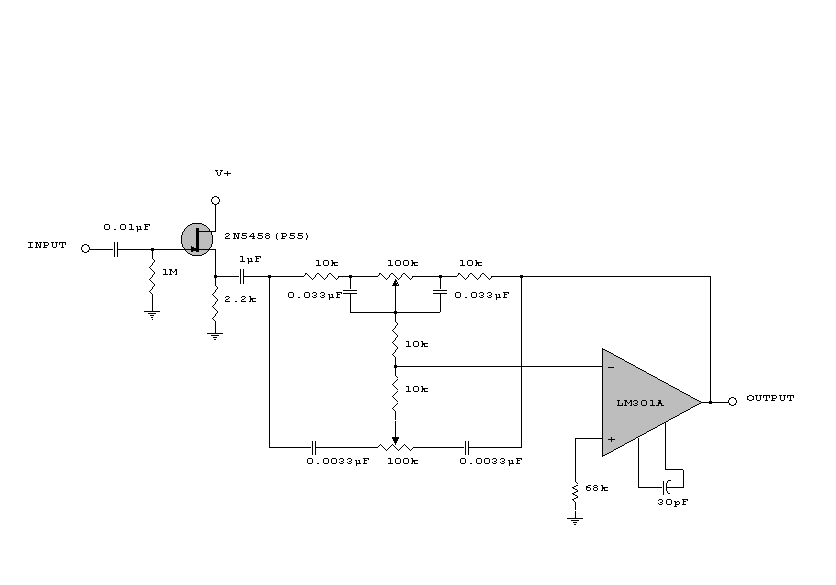
This circuit is a simple series tone control circuit. It utilizes the surgical amplifier LM301A. The JFET 2N3684 provides high input impedance and low noise for the unbuffered operational amplifier, which operates in an equalizer (EQ) configuration. Further details...
Currently, a basic MOSFET amplifier or power amplifier is designed to deliver an output power of ±100 Watts RMS with an 8 Ohm load, or ±160 Watts RMS with a 4 Ohm load. The simplicity of this circuit results...
The circuit illustrated in Figure 3-81 employs a transistor delay circuit to facilitate start-stop cycle control. It can operate in both manual and automatic modes. The circuit is primarily governed by the motor run time circuit, which includes transistors...