
Six a start and stop intermittent cycle control circuits

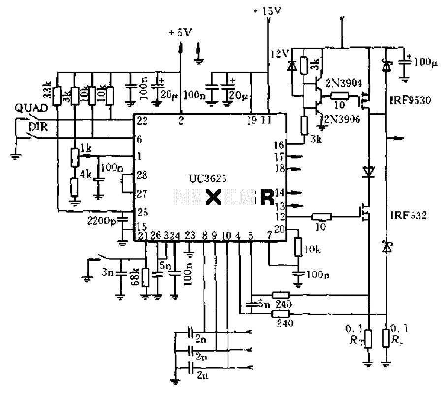
The circuit operates by utilizing a combination of transistors and FETs to manage the timing of the motor's operation. The motor run time circuit is responsible for determining how long the motor remains active during each cycle. Transistor VTi serves as the primary control element, while the FETs VTz and VTa provide additional switching capabilities to ensure efficient operation.
In parallel, the downtime control circuit is designed to manage the intervals during which the motor is inactive. This is crucial for applications that require precise timing and control over motor functions. The FET transistors VT4, VTs, and VT6 play significant roles in this aspect, allowing for rapid switching and reliable performance.
The inclusion of potentiometers RPi and RPz enables users to fine-tune the operation of the circuit. By adjusting these components, the user can extend or shorten the duration of the motor's active and inactive states, providing flexibility to meet specific operational requirements. This adaptability is particularly beneficial in applications where varying motor speeds or operational cycles are necessary.
Overall, the circuit exemplifies a sophisticated approach to motor control, leveraging the versatility of transistors and FETs to achieve efficient start-stop operations. The design ensures that both manual and automatic control options are available, making it suitable for a wide range of applications. Circuit shown in Figure 3-81. The circuit uses a transistor delay circuit to achieve start-stop cycle control. You can take the hand moving and automatic manner. Circuit is pri marily controlled by the motor run time circuit (VTi and the FET transistor VTz, VTa etc.) and downtime control circuit (the FET transistor VT4 and VTs, VT6 etc.) of two parts. Adjust potentiometer RPi and RPz, can change the motor running and stop time.
Related Circuits
The circuit diagram represents a brushless DC motor driving circuit designed for a 45V/8A application. It features an open voltage-controlled design that allows for speed adjustment through an external potentiometer connected to a PWM duty cycle. The diagram illustrates...
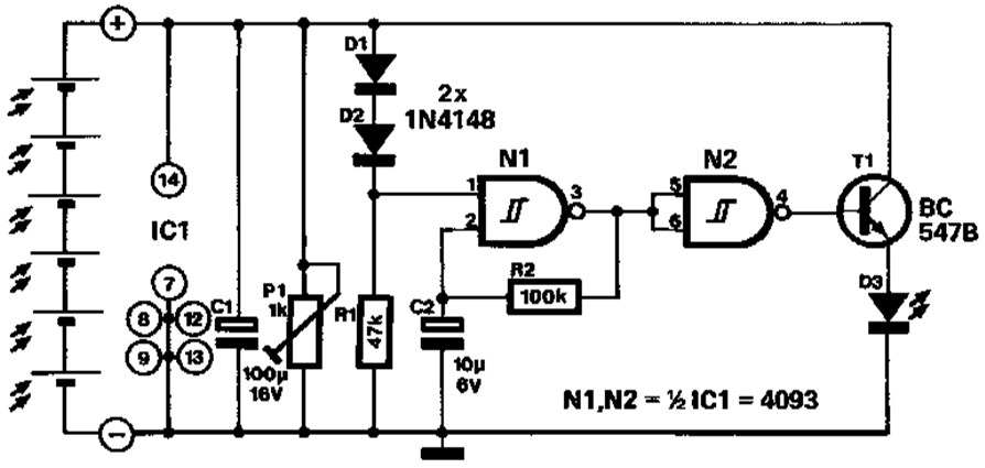
A novel application of solar cells simplifies the process of positioning a car in a garage, offering an improvement over traditional methods such as using old tires, mirrors, or chalk marks. The six solar cells depicted in Figure 1...
This converter allows reception of six metre signals on a two metre receiver. It should therefore be useful for those with single or dual band sets that do not cover 50 MHz. More: To eliminate the need to obtain...
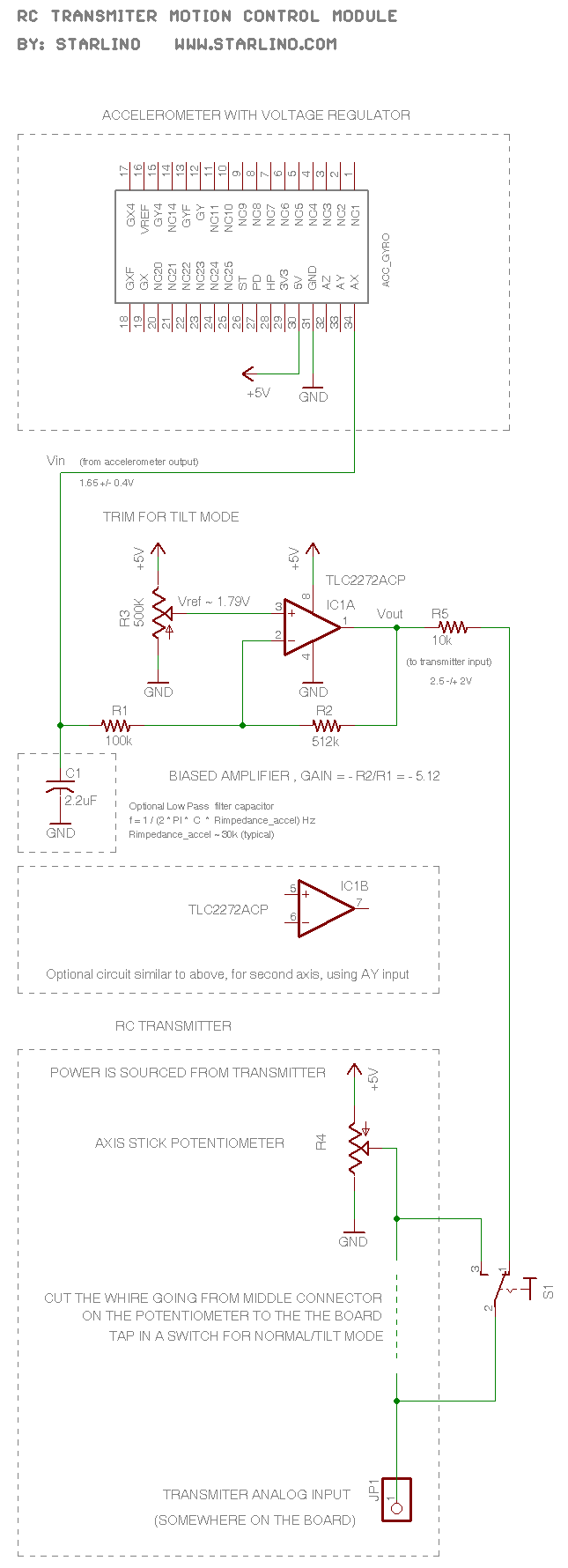
The RC transmitter utilizes a potentiometer for each axis, functioning as a voltage divider that outputs a voltage of 0.5V, with the middle position corresponding to 2.5V. This voltage is sent to the analog input, which is converted into...
The use of a quarter-wave parallel-wire line as a tuning unit has been discussed in the chapter on Short-Lines, where it was pointed out that these circuits have comparatively high Q even at higher frequencies. Their significant length (approximately...
1990 Acura Integra Starting System Wiring Diagram. The 1990 Acura Integra starting system wiring diagram provides a visual representation of the electrical connections and components involved in the vehicle's starting system. This diagram is essential for understanding the layout and...