
2x10 Band Stereo Graphic Equaliser

The 20-band stereo graphic equalizer circuit comprises multiple filter stages, each corresponding to a specific frequency band. The primary function of this equalizer is to adjust the amplitude of audio signals across these bands, allowing for enhanced control over the sound output. Typically, each band is centered around a specific frequency, with the equalizer enabling boosts or cuts to the signal levels as required by the user.
The circuit generally includes a series of band-pass filters, operational amplifiers for signal processing, and potentiometers for user control. Each band-pass filter is tuned to a specific frequency, allowing for precise adjustments in the audio spectrum. The operational amplifiers amplify the filtered signals, ensuring that the output maintains a strong and clear audio quality.
In a typical configuration, the input audio signal is fed into the circuit, where it is split among the various filter stages. Each stage processes the signal corresponding to its designated frequency band. The user can manipulate the potentiometers to either increase or decrease the gain of each band, thus shaping the overall sound profile.
After processing, the combined output from all frequency bands is sent to the amplifier circuit. It is crucial that the equalizer circuit is placed before the amplifier to prevent distortion and to ensure that the amplifier receives a properly balanced signal.
For optimal performance, it is essential to consider component selection, including high-quality capacitors and resistors, to minimize signal degradation. Additionally, careful layout design can help reduce noise and interference, further enhancing the performance of the equalizer circuit. Proper grounding techniques should also be employed to maintain signal integrity throughout the audio processing chain.The following diagram is the circuit diagram of 20 band stereo graphic equaliser which will controlling the audio signal in specific frequency range. This circuit must be connected before the amplifier circuit. For maximum performance, you.. 🔗 External reference
Related Circuits
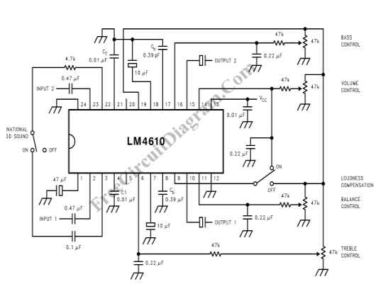
The LM4610 utilizes a DC signal to manage the tone (bass/treble), volume, and balance circuits. The benefits of employing DC control include the ability to operate in mono mode. The LM4610 is an integrated circuit designed for audio applications, specifically...
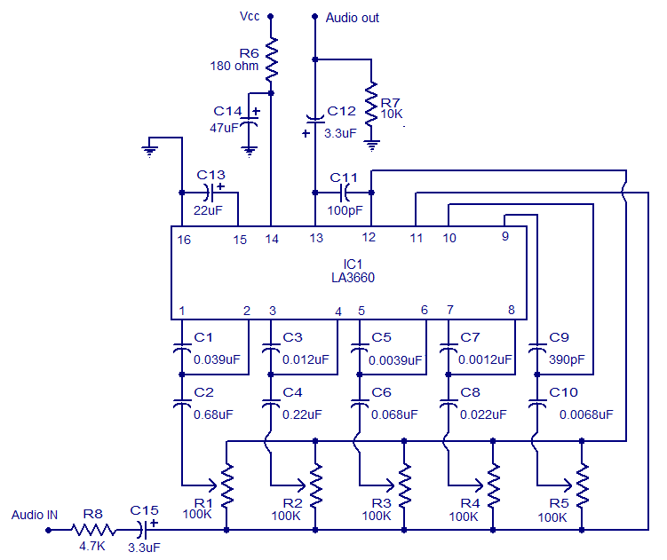
The graphic equalizer described is based on the LA3600 integrated circuit from Sanyo Semiconductors. The LA3600 is a single operational amplifier, 5-band graphic equalizer IC that is well-suited for applications such as portable stereo systems, radios, home theater systems,...
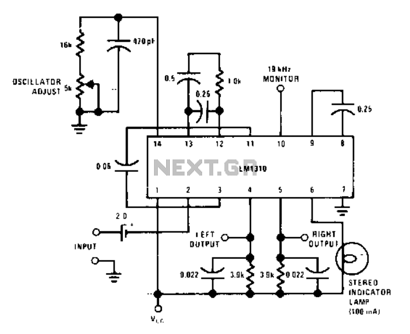
This circuit utilizes a single integrated circuit, the LM1310, to provide left and right outputs from a composite MPX stereo signal. The oscillator adjust resistor R1 is configured for 76 kHz, which corresponds to 19 kHz at pin 10....
Switched-capacitor filters that are preset for a given bandwidth sometimes do not deliver the bandwidth or Q an application requires. By inverting the clock between two switched-capacitor bandpass filters, such as the MSFS1 from Mixed Signal Integration Corp, you...
A 2 x 18W Hi-Fi Stereo Power Amplifier is designed using two TDA2030 integrated circuits (ICs). This amplifier features good input sensitivity, low distortion, stable operation, and comprehensive protection against overloads and output short-circuits. It can serve as a...
The output voltage is = 0.707 x Vin, at the center position. The output voltage is = Vin, at either extreme position. This circuit appears to describe a variable output voltage system, likely utilizing a potentiometer or a similar adjustable...