
Stereo demodulator

The LM1310 is a dedicated stereo demodulator designed for decoding multiplexed stereo signals. It effectively separates the left and right audio channels from a composite signal, making it suitable for applications in audio processing and broadcasting. The circuit's performance is heavily influenced by the choice of components, particularly the capacitor C1, which should be selected as a silver mica or NPO ceramic capacitor to ensure stability and low distortion in the audio output.
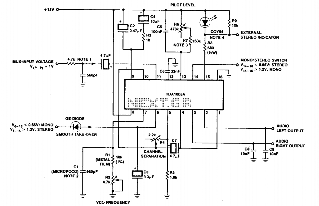
In this configuration, the oscillator circuit within the LM1310 generates a frequency of 76 kHz, which is essential for accurately demodulating the multiplexed signal. The resistor R1 plays a crucial role in setting this frequency, and any variations in its value can significantly affect the performance of the circuit. The output pins provide the separated left and right audio signals, which can be further processed or amplified as needed.
For optimal performance, it is important to maintain proper grounding and shielding in the circuit layout to minimize noise and interference. The selection of high-quality components, particularly in the signal path, will enhance the overall fidelity of the audio output. The design can be adapted for various applications, including FM radio receivers, stereo audio systems, and other multimedia devices requiring stereo signal processing.This circuit uses a single IC LM1310 to proyide left and right outputs from a composite MPX stereo signal. Oscillator adjust Rl is set for 76 kHz (19 kHz at pin 10). C1 should be a silver mica or NPO ceramic capacitor.
Related Circuits
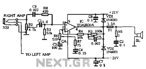
The circuit comprises two main components: the Lisheng power amplifier and the rectifier filter section. The stereo audio power amplifier circuit diagram, depicted in Figure 5-85, illustrates only one channel, with the other channel being identical. The audio signal...
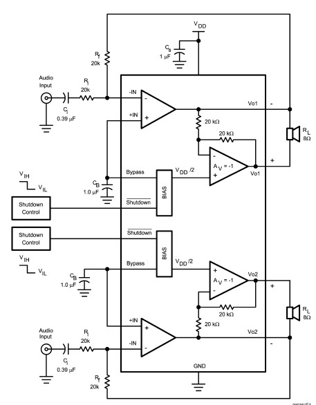
The LM4992 stereo audio power amplifier can be utilized to design a straightforward audio power amplifier project suitable for portable electronic devices. This amplifier circuit is capable of delivering 1 watt of continuous average power per channel to an...
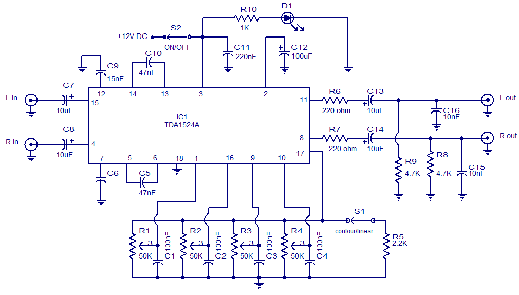
The circuit diagram presents a high-quality stereo preamplifier featuring tone control, utilizing the TDA1524 IC from Philips. This integrated circuit requires minimal external components, operates with low noise, and accommodates a broad power supply voltage range. Potentiometers R1 through...
The FSK demodulator is an electronic device that converts the FSK signal into a serial digital signal. FSK modulation is utilized to transmit digital serial data. The FSK (Frequency Shift Keying) demodulator serves a critical function in digital communication systems...
The circuit depicted includes an RC filter (Figure T). The micropico capacitor has a temperature coefficient of 125 x 10^-6 at 60 x 10^-6°C. In simplified circuits, a fixed resistor, such as 620kΩ, can be utilized to ensure a...
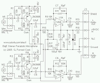
The mini condenser microphone converts sounds into an electrical signal. Resistor R1 provides bias for the condenser microphone's internal amplifier transistor. The 2N3906 PNP transistor acts as a low-noise microphone input amplifier. The 10K gain potentiometer is used for...