
Stereo Tone Control with National 3D Sound

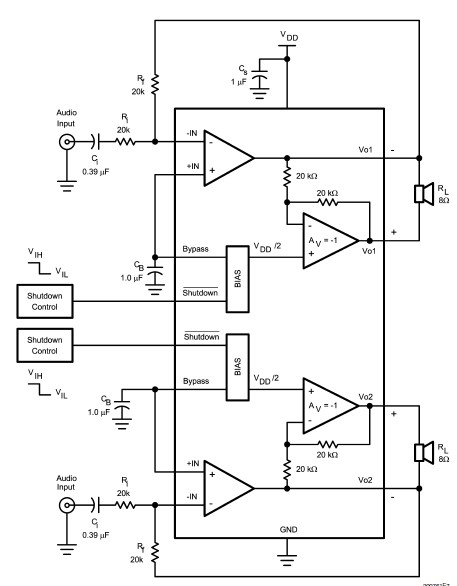
The LM4610 is an integrated circuit designed for audio applications, specifically for controlling various aspects of sound output such as tone, volume, and balance. The use of a DC signal for control allows for precise adjustments and simplifies the design of audio systems.
The tone control feature enables the adjustment of bass and treble frequencies, allowing users to tailor the audio output to their preferences. The volume control function adjusts the overall loudness of the audio signal, while the balance control allows for the adjustment of sound levels between the left and right audio channels, ensuring an optimal listening experience.
One of the significant advantages of using DC control in the LM4610 is its compatibility with mono audio systems. This capability is particularly beneficial in applications where stereo sound is not required, allowing for a more straightforward design and reduced component count. The integration of these controls into a single chip minimizes the need for external components, thereby enhancing reliability and reducing the overall footprint of the audio circuit.
In summary, the LM4610 serves as a versatile solution for audio control, leveraging DC signals to provide efficient management of tone, volume, and balance in both mono and stereo applications. Its design contributes to improved performance and user experience in various audio systems.The LM4610 uses DC? signal to control the tone (bass/treble), volume, and balance circuit.?? The advantages of using DC control is that you can use a mono. 🔗 External reference
Related Circuits
Motor potentiometers are not preferred, particularly when inexpensive and compact attenuators are used with large motors. However, larger blue Alps potentiometers, such as those found on eBay, are favored. Motor potentiometers serve as variable resistors that control the speed or...
The rectifier bridge voltage is determined by the U2 element; refer to its datasheet for the maximum voltage specifications. The minimum voltage at this pin should not fall below approximately 9V, or 6.5V if low-dropout type U2 and U3...
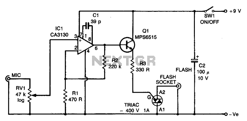
The circuit utilizes an operational amplifier (IC1) configured in a non-inverting amplifier mode. Resistors R1 and R2 establish a gain of approximately 500. The variable resistor RV1 (sensitivity) adjusts the bias of the non-inverting input to the negative supply...
XTAL1 drives amplifier Q3/Q4, which is tuned to 2.25 MHz. The detected signal is fed to audio amplifier IC1. A 9-V supply is used. The circuit operates at 2.25 MHz and is designed to be used with an ultrasonic...
The LM4992 stereo audio power amplifier can be utilized to design a straightforward audio power amplifier project suitable for portable electronic devices. This amplifier circuit is capable of delivering 1 watt of continuous average power per channel to an...
The schematic illustrates a 12 W Bridge Amplifier circuit diagram utilizing the TDA2007A, a class AB dual audio power amplifier. This amplifier is specifically designed for stereo applications in music centers, television receivers, and portable radios. As stated in...