
Computer Controlled Frequency Counter/Logic Probe

The frequency counter circuit employs a stable oscillator to maintain accurate frequency measurements across its specified range. The design incorporates a microcontroller interfaced with the PC's serial port, facilitating communication and data transfer. The microcontroller processes the input frequency signal, converting it into a digital format that can be displayed on the PC.
The calibration process is critical to ensure the accuracy of the frequency readings. By utilizing a known frequency source, the system can adjust for any discrepancies caused by variations in the crystal oscillator used in the PC serial card. This calibration is stored in a dedicated data file (PROBE.DAT), which the frequency counter references during operation to apply the necessary corrections.
The logic probe functionality allows for real-time analysis of digital signals, providing visual feedback of the logic states. This feature is particularly useful for troubleshooting and debugging digital circuits. The software interface provides an intuitive user experience, allowing users to easily navigate through the various functionalities, including frequency measurement and logic analysis.
Overall, this circuit represents a versatile tool for electronic engineers and hobbyists alike, combining frequency measurement and logic analysis capabilities in a compact and efficient design. The reliance on software for calibration and analysis further enhances its usability, making it a valuable addition to any electronics toolkit.This circuit is a stable frequency counter accurate to 5 significant digits. The range is 0 - 30MHz with an input sensitivity of greater then 100mV. The probe connects to the PC serial port. So by using the crystal oscillator already present on your PC serial card and software calibration, the Probes` external circuitry is kept to a minimum. Probe 9 can also be used as a logic probe/analyzer using included software (LPROBE92. EXE). The software to use this probe can be downloaded using the following link. Note that this software is compiled for Intel x86 platforms and runs under DOS, Win95, Win98 and WinMe. It does not run under any Windows version based on NT including Windows NT 3. 51, WinNT4, Win2K, Win2K3, WinXP and Windows Vista. This is because NT based operating systems do not allow direct hardware access. SETPROBE. EXE is the frequency counter calibration program. To give accurate readings the Probe must be calibrated to your PC. SETPROBE. EXE calculates the constant error correction factor for the particular PC serial card the probe is to be used on.
The frequency counter corrects for this slight constant error in crystal frequency by using the correction factor contained in PROBE. DAT. To calculate this correction factor, a reliable oscillator of known frequency (eg 2MHz Crystal Oscillator) is required.
When CALIBRAT. EXE is run, the Probe will sample the frequency and then ask for the true frequency value in HZ. The frequency entered must be to 1 Hz accuracy (no decimal points) or an error will occur (for example "200123" not "200123. 34" or "2003. 421 kHz"). The program then calculates constant error correction factor and stores it to PROBE. DAT. Calibration is only necessary once. LPROBE92. EXE is the logic analysis program. Logic states are displayed in real time. This program runs best under DOS (not a DOS window). The sampling speed is adjusted by using the left and right arrow keys. FPROBE92. EXE is the frequency counter program. The measured frequency is displayed in Hz with commas indicating KHz and MHz. To quit from FPROBE press any key. 🔗 External reference
Related Circuits
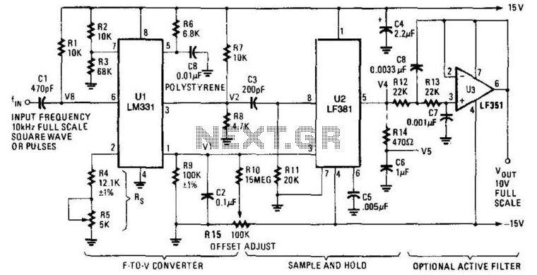
U1 is a frequency-to-voltage converter that feeds a sample-and-hold circuit utilizing an LF381 operational amplifier. An LF351 provides a 10-V maximum scale output. The circuit generates a 1-V output per kHz frequency. The described circuit employs a frequency-to-voltage conversion technique,...
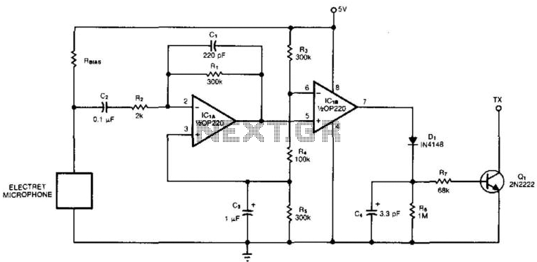
An electret microphone feeds a bandpass filter circuit (IC1A), which subsequently drives a comparator. This comparator activates Q1, a switch that conducts when audio signals from IC1B cause D1, C4, R6, and R7 to bias it ON. The circuit begins...
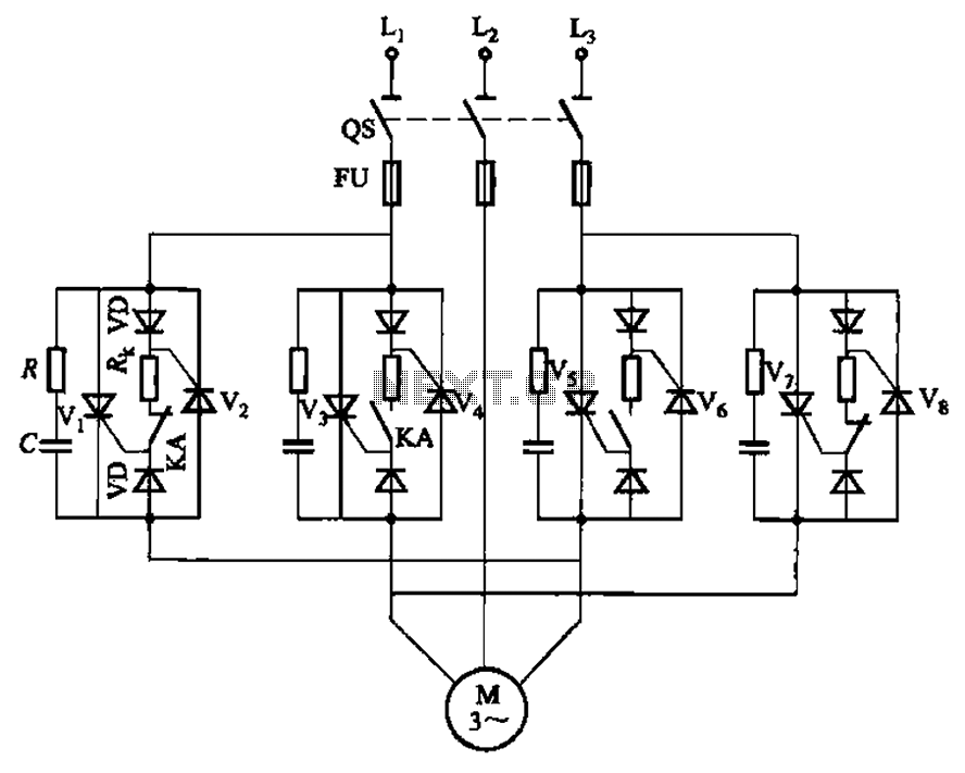
The circuit depicted in Figure 3-69 is designed for applications requiring frequent timing control for motor reversing operations. In this configuration, thyristors V1, V2, V7, and V5 are utilized for positive control of rotation, while thyristors V3, V4, and...
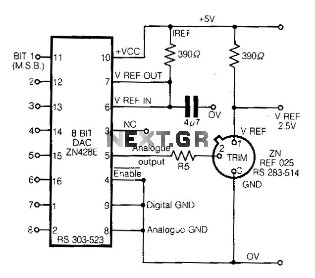
This circuit demonstrates a straightforward approach to achieving a voltage reference that can be adjusted using an 8-bit Digital-to-Analog Converter (DAC) equipped with an integrated voltage reference. The analog output from the DAC controls the trim pin of the...
A function generator that operates within a frequency range of 0.1 Hz to 20 MHz can be easily constructed using the MAX038 integrated circuit chip. This describes a straightforward implementation of the device. The MAX038 is a precision waveform generator...

This is a simple automatic light switch circuit designed for bedrooms. After construction, connect the input terminals of this circuit in parallel to the existing light fixture. The automatic light switch circuit operates using a photoresistor (LDR) and a transistor...