
Audible Logic Probe Circuit Schematic

The circuit utilizes the NE556 timer in a dual configuration, leveraging its ability to generate precise timing pulses. The NE556 is configured as an astable multivibrator, producing a continuous square wave output. The frequency of oscillation can be adjusted by varying the resistors and capacitors connected to the timer. This output is then fed into a logic gate, specifically the SN74132N, which is a quad 2-input NAND gate. This gate processes the incoming signal to determine the transitions between the high (1) and low (0) states.
The audio output is generated by a small speaker or buzzer connected to the output of the NE556 timer. When a transition occurs—either from low to high or high to low—the timer generates a pulse that activates the buzzer, producing an audible beep. The duration of this beep is set to a minimum of 50 nanoseconds, ensuring that the transitions are clearly indicated by sound.
In addition to the audio feedback, an LED is integrated into the circuit to provide a visual cue of the logic state. The LED is connected in such a way that it illuminates when the input logic level is high (1). This dual feedback mechanism—both auditory and visual—allows for effective monitoring of the logic state, facilitating easier debugging and inspection of digital circuits.
Overall, this circuit serves as a practical tool for engineers and technicians, enabling them to diagnose and analyze digital signals with enhanced efficiency and ease. The combination of the NE556 timer’s timing capabilities, the logic processing of the SN74132N, and the output indicators (both audio and visual) create a robust solution for logic state indication.NE556 timer can be used as an indicator of static of digital logic audible terminal. Audible logic probe is useful for inspecting a part visually while we also need to check the logic state on other point far from the part. NE556 acts as an oscillator controlled by (SN74132N) and IC2 (SN7486N). Any logic transition from 0 to 1 and vice versa will be followed with audio beep, lasting at least 50 nanoseconds. LED provide visual indication. When the input logic is 1, the LED will glow. 🔗 External reference
Related Circuits

This circuit schematic produces a beep and/or illuminates an LED when someone touches the door handle from outside. The alarm will continue to sound until the circuit is switched off. The circuit operates on the principle of capacitive sensing, where...
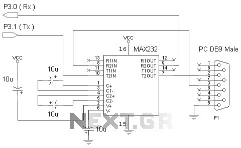
One of the most effective communication methods to be implemented in a digital system is the use of the RS232 serial line. The microcontroller 89S51 is equipped with a UART, allowing it to perform serial communication at RS232 levels...

This example describes the use of HS101 and HS201 radio transmitter and receiver modules to control rotating color lights, functioning as a multi-channel radio remote control device suitable for small dance floors or home use. Users positioned at any...
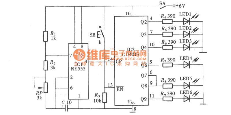
The Reaction Capability Tester is utilized to assess and enhance an individual's quick-response abilities. It features various designs, with the depicted model comprising a CD4017 decimal counter and a light-emitting diode (LED). The construction of the Reaction Capability Tester...
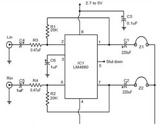
The LM4880 is a dual audio HiFi amplifier integrated circuit from National Semiconductor. This headphone amplifier circuit is specifically designed to produce high-quality audio output with a minimal number of components. The LM4880 integrated circuit is capable of delivering...
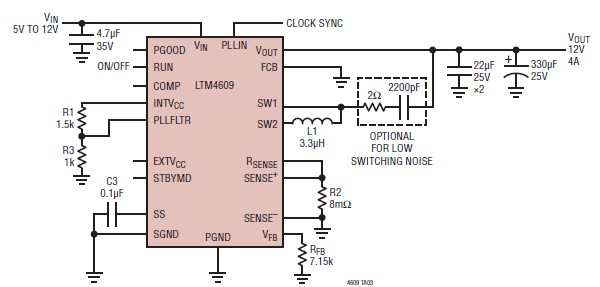
A very simple, high-efficiency switching mode buck-boost power supply circuit can be designed using the LTM4609 switching regulator IC. This circuit will provide a fixed output voltage of 12 volts. As illustrated in the schematic, the switching power supply...