
Need help with strobe circuit

The circuit in question appears to involve a strobe light mechanism, which typically requires precise timing and control signals. The removal of the 1K potentiometer suggests that it was previously used to adjust the intensity or frequency of the strobe effect. In the absence of a breadboard for prototyping, direct modifications to the PCB will be necessary to test and refine the strobe functionality.
To achieve the desired strobe effect, the circuit may incorporate a 555 timer IC configured in astable mode. This configuration allows the circuit to oscillate between high and low states, creating a pulsing effect suitable for strobe lighting. The frequency of the strobe can be adjusted by changing the resistors and capacitors connected to the 555 timer.
In addition to the 555 timer, a transistor may be included to drive the strobe light. The transistor acts as a switch, allowing for higher current to flow through the strobe light than what the timer can provide. A suitable NPN transistor, such as the 2N2222, could be used for this purpose, with the base connected to the output of the 555 timer through a current-limiting resistor.
Power supply considerations are also critical; the circuit should be designed to operate within the voltage ratings of the components used, typically powered by a DC source. Proper decoupling capacitors should be placed near the power pins of the IC to ensure stable operation.
In summary, while the absence of a breadboard poses challenges for testing, modifications to the PCB can facilitate the development of the strobe circuit. The focus should be on optimizing the timing components, ensuring reliable switching through the transistor, and providing adequate power supply stability.Unfortunately I don`t have a breadboard to try this out on but can modify the PCB. I`ve removed the 1K pot till I can get the strobe working and than.. 🔗 External reference
Related Circuits
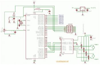
The complete electrical circuit diagram of a line follower robot is based on the ATmega16 microcontroller. This robot consists of three primary modules: the sensor module, the microcontroller module, and the DC motor module. A comprehensive tutorial, including circuit...
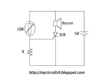
The Light Dependent Resistor (LDR) is a variable resistor whose resistance decreases as light intensity increases. Under normal light conditions, the resistance of the LDR is sufficiently high, resulting in an inadequate voltage across resistor R to activate the...
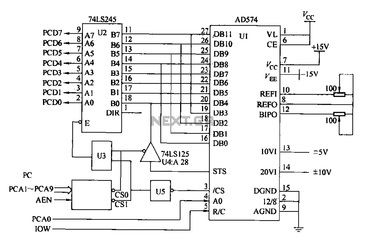
Another example is provided using the AD574 and PC bus. The AD574 converter is represented by U1, while U2 is a 74LS245 bidirectional data buffer. U3 is a 74LS00 two-input AND gate, U4 is a 74LS125 tri-state output gate,...
This circuit is a difference amplifier. It functions as an inverting amplifier that enables the subtraction of two voltages, effectively performing a summation. The difference amplifier is a fundamental circuit configuration in analog electronics, primarily used for amplifying the difference...
Stabilized DC Power Supply with Short-Circuit Indication. The circuit provides four distinct regulated DC outputs (12V, 9V, 6V, and 5V) along with an unregulated 18V DC output, selectable via a rotary switch S2. The chosen output is displayed on...

This circuit is particularly beneficial for hobbyists using a breadboard to experiment with ideas, as well as those employing a simple homemade DC power supply that consists of a transformer, rectifier, smoothing capacitor, and protective fuse, specifically one lacking...