
Light activated logic circuits

The provided circuits serve as examples of fundamental logic functions utilized in digital electronics. Logic functions are the building blocks of digital systems, enabling the execution of various operations such as AND, OR, NOT, NAND, NOR, XOR, and XNOR. Each of these functions can be represented using different types of logic gates, which are the essential components of digital circuits.
1. **AND Gate**: This gate outputs a high signal (1) only if all its inputs are high. It can be represented in a schematic with two or more input lines converging at the gate, with a single output line.
2. **OR Gate**: The OR gate produces a high output if at least one of its inputs is high. Its schematic representation includes multiple input lines leading to a single output line.
3. **NOT Gate**: Also known as an inverter, this gate outputs the opposite value of its single input. The schematic shows one input line leading to the gate and one output line.
4. **NAND Gate**: This gate is a combination of an AND gate followed by a NOT gate. It outputs a low signal only when all its inputs are high. The schematic includes input lines converging at the gate, with the output line indicating the inverted result.
5. **NOR Gate**: This is the opposite of the OR gate, producing a high output only when all inputs are low. Its schematic resembles that of an OR gate but includes an inversion at the output.
6. **XOR Gate**: The exclusive OR gate outputs high when an odd number of its inputs are high. The schematic displays multiple input lines leading to a single output, indicating the exclusive condition.
7. **XNOR Gate**: This gate is the complement of the XOR gate, outputting high when an even number of inputs are high. Its schematic representation is similar to that of the XOR gate but includes an inversion at the output.
These logic functions can be combined in various configurations to create more complex circuits, such as multiplexers, demultiplexers, encoders, and decoders, which are essential in digital communication and processing systems. The understanding and implementation of these basic logic functions are crucial for designing efficient electronic circuits that perform specific tasks within a system.These circuits illustrate some of the common logic functions that can be implemented.
Related Circuits
A circuit was assembled on a breadboard, which is divided into two sections. The right section is dedicated to generating a wailing alarm, while the left section is... The circuit design comprises two main functional blocks: the alarm generation circuit...
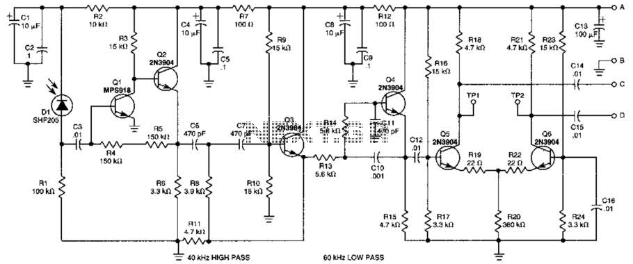
This receiver is designed to detect infrared (IR) or light beams that are frequency modulated on a 50-kHz carrier. The transistors Q2, Q1, Q3, and Q4 form an active filter and amplifier, while the differential amplifier formed by Q5...

The drawing below illustrates a multistage light sequencer using discrete parts and no integrated circuits. The idea is not new and I hear a similar circuit was developed about 40 years ago using germanium transistors. The idea is to...
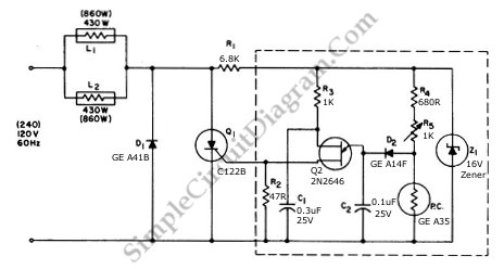
This circuit utilizes a controlled half-plus-fixed half-wave phase control method to regulate an 860-watt lamp load, allowing operation from half to full power. The circuit employs a phase control technique, which involves adjusting the phase angle of the AC...
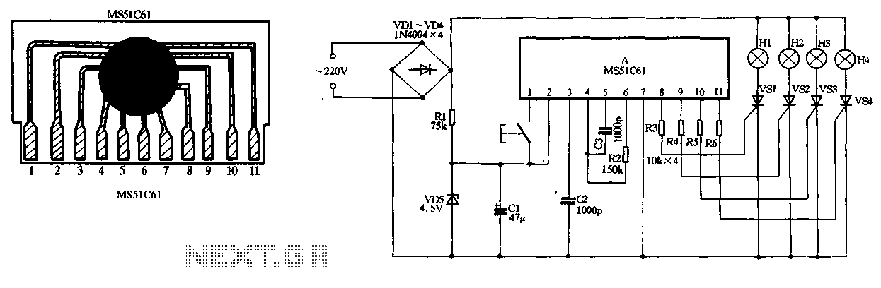
The circuit utilizes a 220V AC input, which is converted to DC using a VD1-VD4 bridge rectifier. This rectified voltage is used to power four lights (H1 to H4). The circuit also includes a resistor (R1) for voltage limiting...
The 555 timer IC is connected for Astable Operation, the clock pulses are fed to the 4017 IC via the 10K resistor. The 4017 is a 10 stage counter, therefore the sequence of the traffic lights is spread over...