
3 LED Car battery Indicator

Specifications:
Operating voltage: 9 - 14V DC
Current operation: 40 mA
Green LED: battery voltage 12 - 13.8 V
Red LED: over voltage 13.8 V
Amber LED: voltage below 12V
The circuit operates within a specified voltage range of 9 to 14 volts DC, making it suitable for monitoring standard automotive battery conditions. The primary components include three LEDs (D1, D2, and D3), resistors (R2, R3, and R5), diodes (D4, Z1, Z2, and Z3), and transistors (TR1 and TR2).
LED D1, colored red, serves as an indicator for under-voltage conditions, lighting up when the battery voltage falls below 12V. This is a critical alert for the user, indicating that the battery may require charging. The circuit achieves this by utilizing a resistor R2 in series with LED D1, ensuring proper current flow and limiting the current to safe levels.
When the battery voltage reaches or exceeds 12V, the circuit activates transistor TR1 via the combination of resistor R5 and zener diode Z3. This action allows for the illumination of LED D2, which is green, indicating that the battery is within an acceptable voltage range of 12 to 13.8V. This state confirms that the battery is functioning properly without any immediate concerns.
As the voltage continues to rise and surpasses the threshold of 13.5V, the circuit engages transistor TR2, which subsequently activates LED D3. This LED serves as a warning indicator for over-voltage conditions, alerting the user that the battery is overcharged and may require attention to prevent potential damage.
Overall, the circuit effectively monitors battery voltage levels and provides visual feedback through the use of colored LEDs, thereby enhancing the user's ability to maintain battery health and avoid overcharging scenarios. The inclusion of zener diodes ensures voltage regulation and stability, contributing to the circuit's reliability and performance in automotive applications.The operating principle of the circuit is very simple. The first Led D1 is placed in series with the resistor R2 and diode D4.An only be lit this LED indicates that the battery is ypofortismeni. For this reason Led D1 is red. If the voltage is greater than 12V, then netting R5 Z3 turns the transistor TR1, so the glows and Led D2 indicates that the battery of your car is okay and that is why color is green.
Now, if the battery voltage exceeds 13,5 V in the same way it lights up and the third LED D3 in the middle of the transistor TR2.Stin cases this increase in voltage is detected by the panel R3 Z1 Z2.Afto means that your battery is yperfortismeni. Specifications: Operating voltage: 9 - 14V DC operation: 40 mA Green LED: battery voltage 12 - 13,8 V Red LED: over voltage 13,8 V Amber LED: voltage below 12V 🔗 External reference
Related Circuits
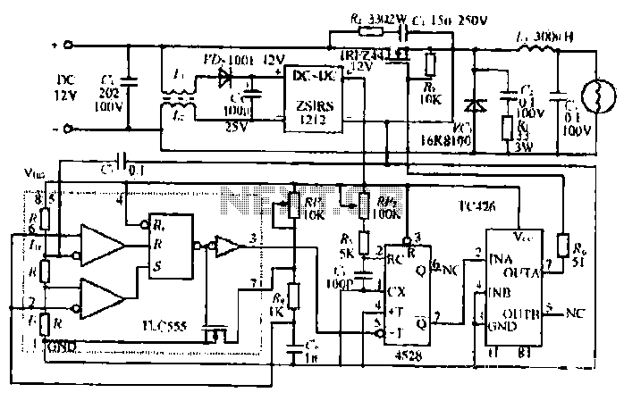
The circuit utilizes a Bute CD12V Lee power MOSFET transistor (BU1RF744) that operates in a switching mode, turning on and off repeatedly. The output voltage is influenced by the characteristics of the MOSFET, which is designed for efficient performance....
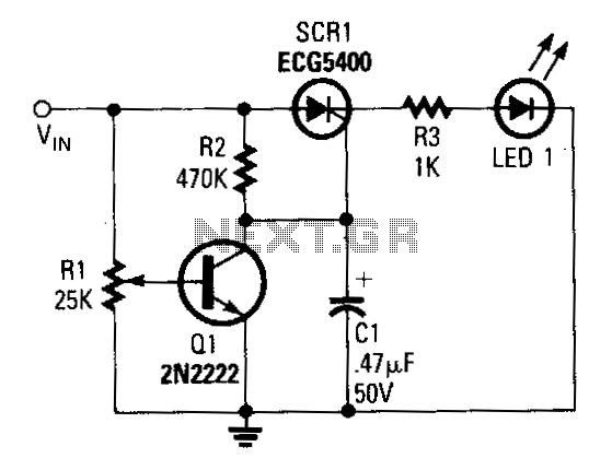
The input terminal VIN is connected to the +V line of the circuit that the indicator is meant to monitor, and the grounds of both circuits are interconnected. The position of the potentiometer R1's wiper determines the base voltage...
A voltage-controlled oscillator (VCO) is an electronic signal generator that produces a signal with a variable frequency, which is dependent on an input voltage level. A voltage-controlled oscillator is a fundamental component in various electronic applications, including phase-locked loops (PLLs),...
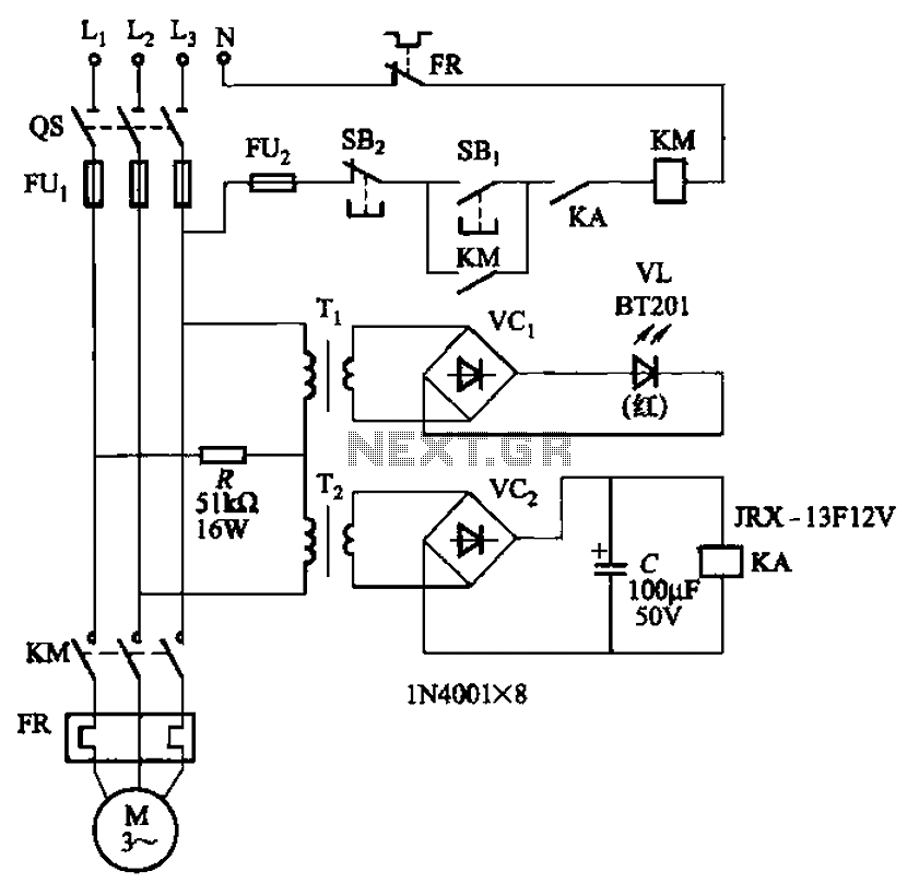
The circuit depicted in Figure 3-92 employs a dual-phase sequence protection relay for sensing. When the power supply exhibits a positive phase sequence (U, V, W), the relay KA is activated. If the power supply maintains the correct phase...
This automatic NiCd charger for 9V NiCd batteries utilizes the properties of a 555 timer and is straightforward to construct. The design allows for continuous charging of the battery without the risk of overcharging or discharging. With the specified...
The drawback of the circuit mentioned is that the operational amplifier (op-amp) supply is connected to the high voltage (HV) supply. Most op-amps are limited to approximately 30V for their supply voltage, which prevents the circuit from functioning with...