
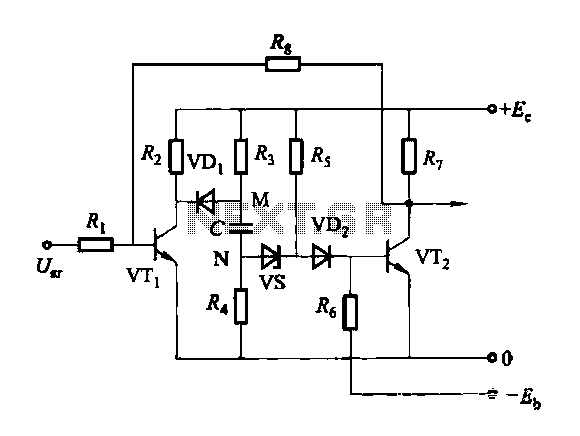
Allowing only one-way operation of the motor-controlled circuit 2

The circuit functions as a protective mechanism for three-phase motors, ensuring that the motor operates only under correct phase conditions. The dual-phase sequence protection relay monitors the incoming phase sequence and activates the relay KA only when the sequence is correct. If any phase is out of order, KA will release, which interrupts the operation of contact KM, thus preventing potential damage to the motor due to incorrect phase conditions.
The use of transformers T1 and T2 with specified turns ratios is crucial for stepping down the voltage levels to manageable values for the relay and other components. The 100:1 ratio for T1 allows for significant voltage reduction, making it suitable for the relay's operating voltage requirements. Similarly, T2 with a 100:3 ratio serves to further adjust the voltage for additional circuit components, ensuring that all elements operate within their rated limits.
The alarm system integrated into the circuit is indicated by diode VL, which provides visual feedback when the relay KA is activated. This feature is essential for operators to quickly assess the operational status of the motor and the phase sequence. The overall design of the circuit prioritizes safety and reliability, ensuring that the motor remains protected against phase sequence faults, which can lead to overheating, mechanical failure, or other electrical hazards.
In summary, the circuit represented in Figure 3-92 is a sophisticated solution for phase sequence protection in three-phase systems, utilizing relays and transformers to maintain operational integrity and provide alerts for any anomalies. Circuit shown in Figure 3-92. It uses dual-phase sequence protection relay sense. When the power positive phase sequence (U, V, w), following the electrical KA pull. If the pow er supply phase sequence right, KA release, contact KM can not pull the motor does not work. Same time emitting diode VL light alarm. FIG transformer Ti, Tz becomes ratios of 100: 1 and 100: 3. A rated voltage of 380V, capacity is the number of VA.
Related Circuits
Discharge before memory circuit. Before the memory circuit is activated, a delay reset circuit is required. When the input signal triggers an action, timing begins, and after a specified delay, the circuit reverts to its original state. During this...
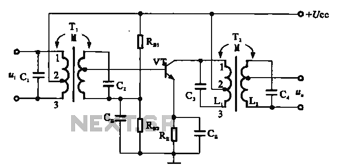
There are two resonant circuits in a double-tuned amplifier circuit, which consists of transformers T1 and T2 with primary and secondary coils that include parallel resonance capacitors. This circuit exhibits a resonance function and can be classified based on...
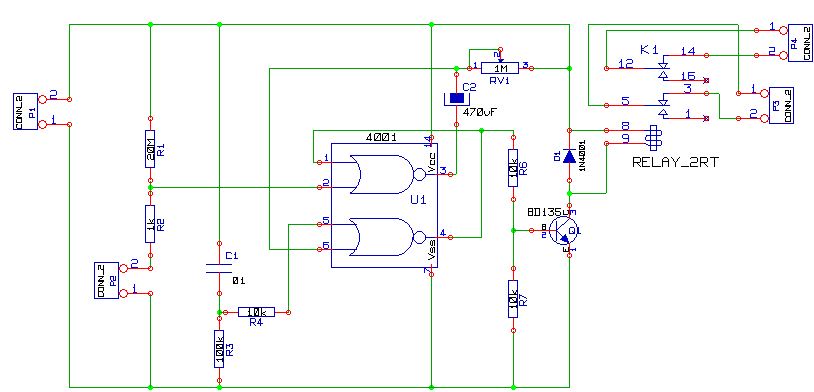
This is a simple alarm circuit using a CD4001 integrated circuit. It is designed for home, motorcycle, car, or other applications. The circuit will undergo computer simulation using Livewire, followed by printed circuit design with KiCad. SW1 is a...

This temperature meter utilizes the precision micro power centigrade sensor IC LM35. The output voltage of the IC is linearly proportional to 10 mV per degree centigrade. The LM35 temperature sensor is a versatile and widely used device in electronic...
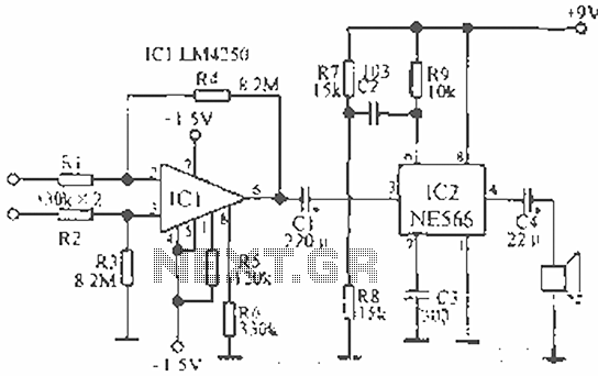
The circuit is designed for teaching demonstrations or experiments to hear the electrocardiogram (ECG) signal voltage. The ECG signal voltage is amplified by the LM4250 operational amplifier, which is connected to a voltage-controlled oscillator (NE566) to modulate the oscillator...
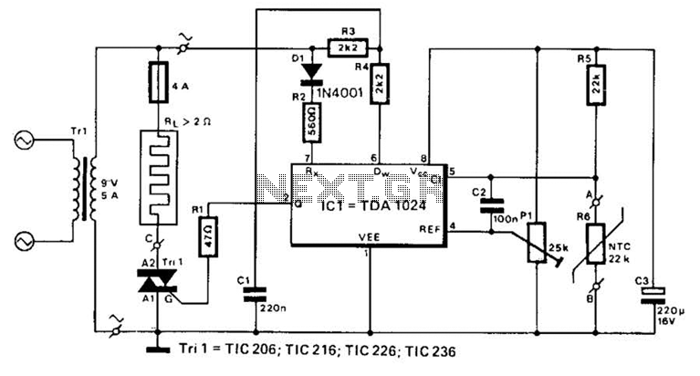
A TDA1024 electronic thermostat measures soil temperature using thermistor R6. The circuit employs zero-crossing switching to control the heater, which is constructed from elastic-coated steel wire. A potentiometer (PI) is utilized to adjust the temperature setting. The heater must...