
3 Watt FM transmitter
The circuit described is a wideband FM transmitter designed to operate within the frequency range of 88 to 107 MHz, suitable for short-range audio broadcasting. The transmitter utilizes a 12 V stabilized power supply with a current rating of 0.7 A, which provides the necessary power for the circuit's operation, including the RF output stage.
The output stage is capable of delivering 3 W of RF power, which is sufficient to drive two 24 V / 3 W bulbs connected in parallel as indicators of the transmitter's output power. The light intensity of these bulbs serves as a visual indication of the transmitter's operational status. The impedance of the output stage is designed to match typical antenna systems, operating effectively within the range of 50 to 75 ohms.
The circuit employs a Phase-Locked Loop (PLL) for frequency stabilization, which allows precise tuning of the transmitter frequency. The tuning process involves adjusting the coils, particularly L1, to achieve the desired frequency. The tuning voltage at capacitor C4 should be maintained within the range of 4 to 9 V for optimal performance. The use of trimmer capacitors C15, C16, and C17 enables fine-tuning of the output power, ensuring that the bulbs reach their maximum brightness, indicating the highest RF output.
Audio input can be connected to the transmitter, and the audio levels can be adjusted using variable resistor R1 to ensure that the audio output is comparable in loudness to other stations. The circuit's performance can be enhanced by using a well-placed outdoor dipole antenna, which can extend the transmitter's coverage range significantly, with reported ranges of up to 1500 meters under normal conditions and a maximum range of 20 kilometers under optimal conditions.
The components list includes various capacitors, resistors, coils, diodes, and transistors, each selected for their specific roles within the circuit. The capacitors range from electrolytic types for power supply filtering to ceramic types for RF applications. The coils are air-core types, allowing for a lightweight design while providing the necessary inductance for RF operation. The choice of transistors for amplification stages ensures reliable operation and good performance characteristics.
Overall, the described circuit represents a practical solution for FM transmission, combining simplicity with effective performance, suitable for hobbyists and educational projects in the field of radio frequency communication.Connect two 24 V / 3 W bulbs in parallel to the output and set the right frequency on PLL. Now turn on the transmitter. You should tune it on a receiver. Maybe you might stretch coils of the L1. Fix the L1 in position when the tuning voltage (on C4) is in range 4-9 V. Then use C15, C16 and C17 to adjust the highest power (the highest light of the bulbs). Then you can connect antenna and audio signal. Adjust R1 until the audio sounds as loud as the other stations. With good antenna (dipole placed outdoor and high) the transmitter has very good coverage range about 1500 meters, the maximal coverage range is up to 20 km. Power supply: 12 V stab., 0,7 A. RF power: 3 W. Impedance: 50-75 ohm. Frequency range: 88-107 MHz. Modulation: wideband FM. Parts list: Capacitors: C1 - 4,7 uF (electrolytic) C2 - 0,22 uF (electrolytic) C3, C4, C12 - 100 pF (ceramic) C6, C9, C11, C13, C14, C19 - 1 nF (ceramic) C7, C8 - 10 pF (ceramic) C10 - 8.2 pF (ceramic) C18 - 22 pF (ceramic) C15 - trimmer 47 pF C16, C17 - trimmer 60 pF C20, C5 - 100 nF (ceramic) C21 - 470 uF (electrolytic) Coils: (All coils are free-standing air-core types, wound of 0,7 mm Cu wire, 6 mm internal diameter.) L1, L6 - 4,5 coils L3 - 2,5 coils L4 - 1,5 coils L2 - 6,5 coils around R9 resistor L5 - 9,5 coils L7 - 3,5 coils Resistors: R1 - 10 k pot. R2 - 4,7 k R3, R4, R5, R8, R10 - 27 k R6, R16 - 10 k R7, R15 - 470 R9 - 100 R11 - 270 R12 - 1 k R13 - 43 R14 - 10 Diodes: D1, D2 - BB109G, BB409 or BBY31 Transistors: T1 - BC547C (BC548C, BC547B) T2 - BFR91A (BFR96) T3 - BFR96S T4 - 2SC1971
🔗 External reference
Related Circuits
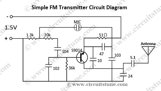
This is a simple FM transmitter circuit schematic diagram that utilizes a single transistor, S9014. The FM transmitter circuit operates by modulating an audio signal onto a carrier frequency, which is typically in the FM band. The S9014 transistor serves...
This transmitter is PLL controlled and the frequency is very stable and can be programmed digitally. The transmitter will work from 88 to 108 MHz and the output power is up to 500mW. With minor changes the frequency can...
The project involves the development of a miniature transmitter suitable for implantation in a rat's body, capable of transmitting 416-bit data samples at a rate of 400 samples per second. It is designed to have a detection range of...
The goals were achieved by utilizing a discrete-component operational amplifier (op-amp) driving a bipolar junction transistor (BJT) complementary common-emitter output stage configured for Class B operation. In this configuration, the output transistors remain off for small output currents, allowing...
The SW transmitter circuit is based on the IC BEL1895 and operates in the shortwave HF band (6 MHz to 15 MHz). It is suitable for short-range communication and educational purposes. The circuit comprises a microphone amplifier, a variable...
This is the basic FM transmitter that I built. In theory, according to electronics, it shouldn't work but works fine and is very sensitive. It can transmit the signal up to 45 yards (about 40 meters). A sensitive FM...
Warning: include(partials/cookie-banner.php): Failed to open stream: Permission denied in /var/www/html/nextgr/view-circuit.php on line 713
Warning: include(): Failed opening 'partials/cookie-banner.php' for inclusion (include_path='.:/usr/share/php') in /var/www/html/nextgr/view-circuit.php on line 713