
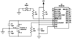
Simple FM Transmitter Circuit Schematic

The FM transmitter circuit operates by modulating an audio signal onto a carrier frequency, which is typically in the FM band. The S9014 transistor serves as the primary amplification and modulation component. In this configuration, the circuit consists of several essential components including a power supply, audio input, the S9014 transistor, a feedback resistor, a tuning capacitor, and an antenna.
The power supply provides the necessary voltage for the operation of the circuit, typically ranging from 9V to 12V. The audio input, which can be connected to various audio sources such as a microphone or audio output from a device, is coupled to the base of the S9014 through a coupling capacitor. This capacitor blocks any DC component from the audio source while allowing the AC audio signal to pass through.
The transistor S9014 is configured in a common emitter arrangement, which provides voltage gain and allows for frequency modulation of the carrier signal. The modulation occurs as the audio signal varies the base current of the transistor, thereby changing the collector current and, consequently, the output signal.
A feedback resistor is connected from the collector to the base of the transistor to provide stability and control the gain of the circuit. The tuning capacitor, in conjunction with an inductor (not specified in the original description, but typically included in FM transmitter circuits), forms a resonant LC circuit that determines the output frequency of the transmitter. This allows the user to tune the transmitter to a specific frequency within the FM band.
Finally, the antenna, which can be a simple wire, is connected to the output of the circuit. It radiates the modulated signal, enabling it to be received by standard FM radio receivers within its range. Proper tuning and adjustment of the circuit components are essential for optimal performance and to ensure compliance with local regulations regarding FM transmission.This is a simple FM transmitter circuit schematic diagram with a single transistor S9014.. 🔗 External reference
Related Circuits
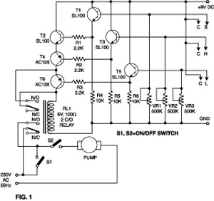
This simple water detector circuit utilizes alternating voltage to prevent the corrosion of the electrodes. It is straightforward to construct and employs N1 as a trigger Schmitt gate that generates the AC signal. When an electrical conductor, such as...
The following file contains detailed information about the design of a basic clock oscillator circuit diagram. Included in this file is information about selecting the components. The clock oscillator circuit is a fundamental component in various electronic systems, providing a...

Fluorescent lamps, despite their long presence, remain enigmatic to many individuals due to their complex operational mechanisms. The lamp consists of a gas mixture, primarily containing mercury, which, when energized as an arc, produces a significant amount of short-wave...

The hobby circuit described utilizes a unique approach to generate approximately 12,000 volts with a current of about 5 µA. It employs two silicon-controlled rectifiers (SCRs) that form dual pulse generator circuits. These SCRs discharge a 0.047 µF capacitor...
This document explains how to connect lights so that they flash when the phone rings. This setup is particularly beneficial in noisy environments, such as workshops, where it is challenging to hear the phone ringing. The ring detection component...

The Clock Controller was designed to be an exemplary of using 'C' language to control timer0 interrupt, 7-segment LED and keypad scanning. It provides 1-bit sink current driving output, for driving a relay, opto-triac, say. Many projects requiring 7-segment...