
30 Meters CW transmitter

The described transmitter operates within the 30-meter amateur radio band specifically for Morse code communication, utilizing a Colpitts oscillator configuration. The primary component responsible for signal generation is the 2N2219(A) transistor, chosen for its robustness in low-power applications, providing an output power range of 100 to 500 mW based on the supply voltage, which can be adjusted between 5 to 20 volts.
The oscillator's frequency stabilization is achieved through a 10 MHz crystal, ensuring precision in signal transmission. A 150 pF trimmer capacitor can be added in parallel with the crystal to allow for slight frequency adjustments, accommodating variations in component tolerances or environmental factors.
The output signal is derived from the collector of the second transistor (Q2) through a Chebyshev low-pass filter. This filter is constructed using standard E12 values, ensuring effective harmonic suppression, which is crucial for maintaining compliance with amateur radio regulations. The prototype demonstrated harmonic rejection levels of 40 dB at 20 MHz and 50 dB at 30 MHz, indicating effective filtering performance.
Keying of the oscillator is managed by the first transistor (Q1), which operates as a switch. When the Morse key is open, Q1 is biased, grounding its base and preventing oscillation. When the key is pressed, Q1 is turned off, allowing Q2 to oscillate freely, thus generating the Morse code signal.
The design incorporates a specific coil configuration for L4, consisting of six primary turns and three secondary turns of 0.5 mm magnet wire wound on an Amidon T-94-2 toroidal core. The core dimensions and inductance characteristics are critical for achieving the desired performance, with the specified dimensions ensuring efficient magnetic coupling and stability.
Thermal management is essential for the reliability of the circuit, particularly for Q2, which requires a heatsink (coolrib) to dissipate heat effectively. The entire assembly should be housed in a metal or aluminum enclosure to provide shielding from electromagnetic interference and to enhance the thermal performance of the circuit. If a metal enclosure is not available, self-adhesive aluminum tape can be employed to create a conductive shield, provided that all sections are electrically connected.
For optimal performance, a double-sided printed circuit board (PCB) layout is recommended, which aids in minimizing parasitic inductance and resistance, thus enhancing the overall efficiency of the transmitter.This transmitters' intended purpose is for morse-code only in the 30 meter band (10Mhz). It is a low-power QRP type and needs to be connected to your existing tranceiver. The harmonic rejections on the prototype were measured at 40dB on 20Mhz and 50dB on 30Mhz. The transmitter is build as a Colpitts Oscillator with a strong 2N2219(A) transistor. HF-output of the oscillator is 100 to 500 mW, depending on the supply voltage of 5 to 20 Volts. The transmit frequency is stabilized with the 10Mhz crystal. A slight detuning is possible by putting a 150pF trimmer capacitor between C2 and the xtal. The oscillator signal is taken from the collector of Q2 by induction and via a low-feedthrough filter and guided to the output. This particular filter is called "Chebychev" and uses standard E12 type values. The oscillator is keyed by Q1, which biases as long as the morse-key is open and the base of Q1 is at ground level.
By keying the morse-key Q1 is blocked and allows Q2 to freely oscillate. For best results, use the double sided pcb as shown above. Coil L4 exists of Primary 6 turns and secundary 3 turns of 0.5mm magnet wire on a Amidon T-94-2 donut. Outside diameter is 24 mm and inside diameter is 14mm; the A(l) value is 84µH per 100 turns and permeability of 10.
Q2 needs a coolrib! The whole circuit needs to be mounted in an all-metal/aluminum case. If you're unable to obtain an all-metal case, then use a roll of self-sticking aluminum tape (available from your hardware store), just make sure that all individual pieces of aluminum-tape are conducting with each other. Works fine. Don't forget the coolrib on T2. 🔗 External reference
Related Circuits

This is a small battery-operated tracking transmitter that broadcasts a repeating radio signal detectable by a directional antenna. The transmitter emits an isotropic signal across the FM band, specifically between 87 to 108 MHz. An ordinary FM radio can...
The transmitter circuit described here includes an additional RF power amplifier stage following the oscillator stage, which increases the power output to 200-250 milliwatts. When used with a properly matched 50-ohm ground plane antenna or a multi-element Yagi antenna,...
The following circuit illustrates the IC BA1404 used in a stereo FM transmitter circuit diagram. Features include ease of construction, making it accessible for anyone to build. The BA1404 is a versatile integrated circuit designed specifically for FM transmission applications....
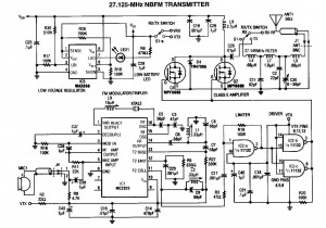
A 27MHz NBFM transmitter circuit schematic featuring the MC2833 and two MPF6660 FET transistors. Utilizing the Motorola MC2833 one-chip FM transmitter along with several supporting components and an MPF6660 RF amplifier, this transmitter can deliver up to 3W into...
TR1 (BC547) is an inverted Hartley oscillator which based upon an inductor fabricated on the PCB. This makes it megga-stable, and setable anywhere in the VHF FM band (76MHz to 119MHz) and the BB105 varicap makes it voltage tuneable...
This circuit transmits a continuous audio tone on the FM broadcast band (88-108 MHz), which can be utilized for remote control or security applications. The circuit draws approximately 30 mA from a 6-9 volt battery and has a reception...