
IC BA1404 For Stereo FM Transmitter

The BA1404 is a versatile integrated circuit designed specifically for FM transmission applications. It operates within a frequency range suitable for stereo audio signals and can be utilized in various projects requiring wireless audio transmission. The circuit typically includes essential components such as resistors, capacitors, and an antenna, which work together with the BA1404 to modulate audio signals onto a carrier frequency.
Key features of the BA1404 include low power consumption, which is advantageous for battery-operated devices, and built-in pre-emphasis circuitry that enhances audio quality by boosting high frequencies. The circuit can be easily assembled on a breadboard or a printed circuit board (PCB), allowing for flexibility in design and testing.
In a typical configuration, the audio input is fed into the BA1404 through a coupling capacitor, which blocks any DC components while allowing the audio signal to pass. The modulation process occurs internally, where the audio signal is superimposed onto the carrier frequency generated by the IC. The output stage of the circuit usually connects to an external antenna, which radiates the modulated signal over the airwaves.
Careful attention should be paid to the layout of the circuit to minimize interference and ensure optimal performance. Proper grounding techniques and shielding may be employed to enhance the circuit's stability and reduce noise. Additionally, selecting the appropriate values for resistors and capacitors can fine-tune the transmitter's frequency response and output power.
Overall, the BA1404 FM transmitter circuit represents an excellent project for electronics enthusiasts, providing a practical application of analog signal processing and wireless communication principles.The following circuit shows about IC BA1404 For Stereo FM Transmitter Circuit Diagram. Features: easy enough for everyone to build, has a .. 🔗 External reference
Related Circuits
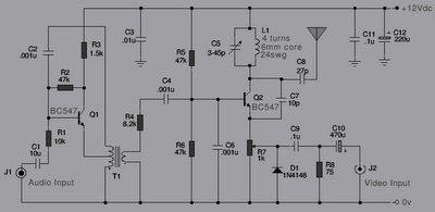
The following is a series of simple TV transmitters utilizing negative sound modulation and PAL video modulation. This design is suitable for countries employing TV systems B and G. Inductor L1 can be constructed using 24 SWG wire, consisting...
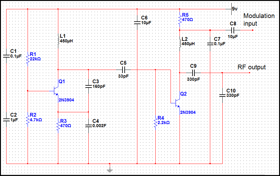
In many discussions of LPAM transmitter design, references to "the Wenzel circuit" or "the Wenzel transmitter" are common. These terms refer to a clever transmitter design that became popular in the mid-1990s and early 2000s for those interested in...
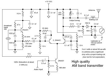
This transmitter is basic but allows the transmission of audio to an AM radio. It consists of an RF oscillator operating in the AM broadcast band, along with a modulator stage that mixes the incoming audio with the RF...
This application note outlines the use of the MAX2361 quadrature transmitter integrated circuit (IC) within the Korean Personal Communications Service (PCS) band, specifically for transmission frequencies ranging from 1750 to 1780 MHz. The MAX2361 is a high-performance quadrature transmitter designed...
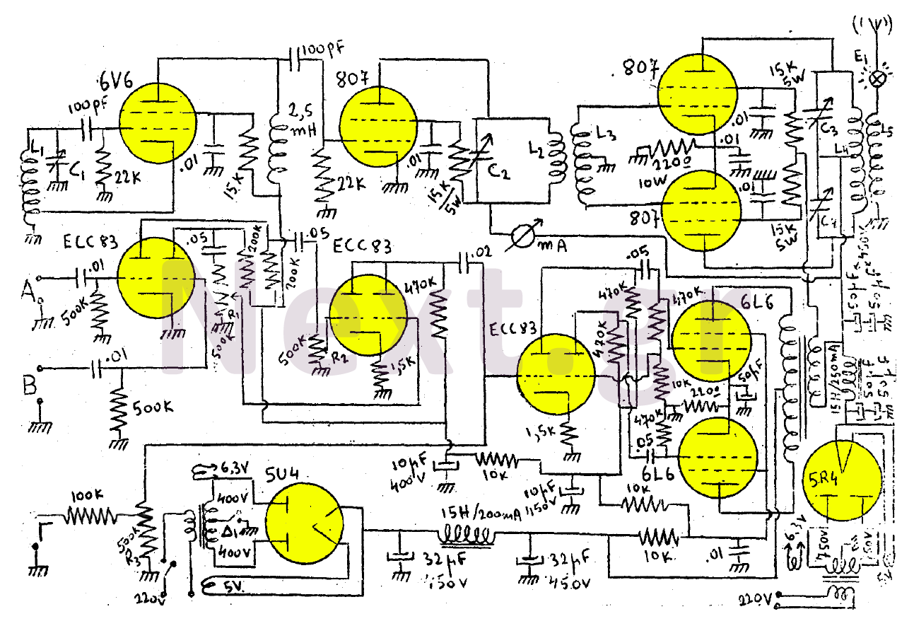
This transmitter consists of a 6V6 oscillator that excites an 807 buffer. The final stage includes two 807 tubes arranged in a Push-Pull configuration. The amplifier is built with three series-connected double-triodes (ECC83) and concludes with two 6L6 tubes...
This is it. It's a STEREO LED LEVEL METER. It's the cheapest and best bar graph display available and best of all, it uses readily available components. You only need a handful of LEDs, 22 transistors, some resistors, diodes,...