
Tracking Transmitter

The small battery-operated tracking transmitter is designed for efficient signal transmission and reception. It operates within the FM band, making it compatible with standard FM radios, which enhances its usability. The Hartley oscillator configuration is notable for its simplicity and effectiveness in generating stable frequencies, making it ideal for tracking applications. The adjustable frequency feature allows users to fine-tune the transmitter for optimal performance in various environments.
The modulation technique employed, utilizing a square wave, introduces harmonics that can be beneficial for signal detection. This characteristic may result in a "dirty" signal, but it enhances the transmitter's locatability, which is a critical aspect of tracking systems. The careful selection of components, such as the CD4011 gates for modulation, demonstrates the design's focus on achieving a reliable output.
The construction of the inductor L1 is a key element in the tuning process. The specified wire gauge and winding technique ensure that the inductor meets the desired inductance value. The ability to adjust inductance by compressing or expanding the coil turns provides flexibility in achieving the required resonant frequency, which is essential for the transmitter's operation.
Overall, this tracking transmitter exemplifies a well-thought-out design that balances simplicity, effectiveness, and user adaptability, making it a valuable tool for various tracking applications.This is a small battery operated Tracking transmitter which broadcasts a repeating radio signal which can be detected by a directional antenna. The transmitter broadcasts an isotropic (radiates in all directions) signal on the FM band. An ordinary FM radio can be used to locate the transmitter, the reception of the signal will improve when the rad
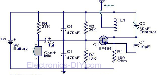
io antenna is pointed in the direction of the transmitter. The transmitter is a standard hartley oscillator, designed to transmit across the FM band approximately, 87 to 108MHz. The transmit frequency is adjustable by means of trimmer C8. The combined capacitance of C4 plus C8 and L1 set the resonant frequency. Modulation for the transmitter is an interrupted square wave signal using all 4 gates of a CD 4011. Gates U1 and U2 interrupt the signal at about 2Hz while gates U3 and U4 create a higher tone in the audio range.
The output of U4 applies this modulation to the base of Q1 via R3. Because the modulation is a squarewave, the radiated signal becomes a little bit "dirty" and harmonics will be heard across the FM band. This is not a big problem as it will aid in locating the transmitter. The transmitter is tuned by the tank circuit L1 and parallel capacitance of C4 plus C8. L1 is approximately 0. 15 uH. The value of "C" in the equation below is the sum of C4 plus C8. L1 is 7 turns of 20swg wire wound on a 6 mm drill bit. This forms an inductor of approximately 150 nH. The value of the inductance can be altered by compressing or expanding the turns. Hold one end of the wire against the drill bit and start to wind the turns clockwise. Continue until all 7 turns have been completed, and the coil looks like the image of the right hand side.
Trim any excess wire so both ends are same length and scrape about 3mm of insulation off the opposite end. For anyone wishing to wind their own coils, Ron J kindly submitted a javascript calculator, on my tuned circuit page.
It is presented here again for convenience. For example using a diameter of 6mm (0. 6cm) and 1cm length, a desired inductor of 0. 15uH works out at 7. 33 turns. 🔗 External reference
Related Circuits
The circuit consists of a frequency modulated oscillator, an audio preamplifier with pre-emphasis to supply the frequency modulating signal, and a buffer amplifier to drive the antenna connector. Oscillator's frequency is determined by L1 resonating with the 10 pF...
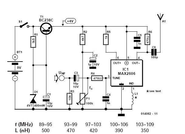
To achieve independence from local radio stations when testing VHF receivers, a frequency-modulated oscillator is required that operates within the range of 89.5 to 108 MHz. However, constructing such an oscillator using discrete components can be quite challenging. Maxim...
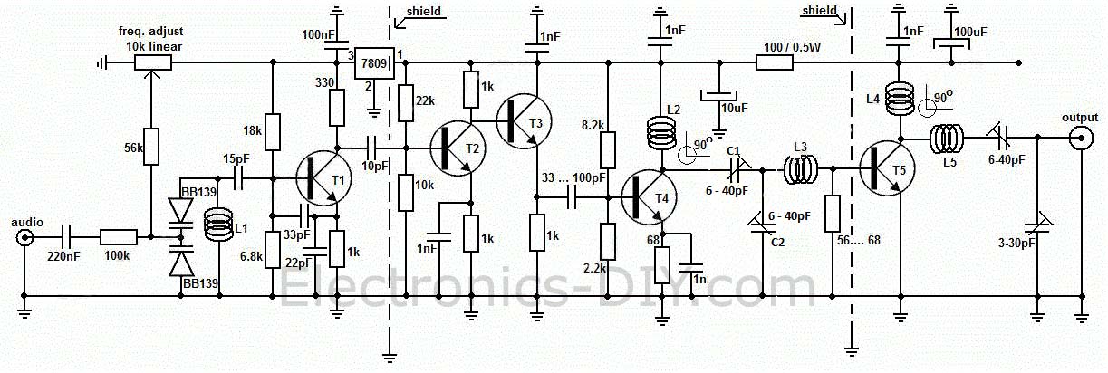
This circuit is a long-range, highly stable, harmonic-free FM transmitter designed for FM frequencies between 88 and 108 MHz. With an appropriate antenna, it can cover a range of up to 5 km. The circuit features a stable oscillator...
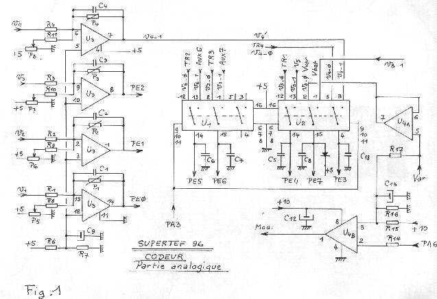
The first SUPERTEF version was using a 68HC11 microprocessor in extended mode i.e. with an external memory program which necessitated many integrated circuits (IC) such as the 74C138, 74C373, 68HC24 and 27C64 making the printed circuit board densely populated...
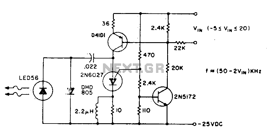
The basic circuit operates at a frequency of 80 kHz, which is constrained by the combination of the PUT (Programmable Unijunction Transistor) capacitors. The maximum modulation frequency achievable is 60 kHz. The pulse repetition rate is directly proportional to...
The circuit diagram of a simple FM transmitter utilizing a transistor is presented. While this design may not guarantee exceptional performance or range, it serves as a fundamental example. The circuit employs a general-purpose radio frequency transistor, the BF...