
FM Crystal Controlled Transmitter DPT

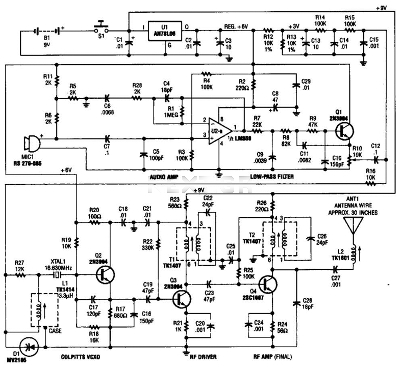
The DPT Transmitter circuit is designed to accommodate varying power requirements, making it suitable for applications that necessitate flexibility in transmission range and battery efficiency. The dual-power functionality is achieved through a simple switch mechanism, allowing users to toggle between high and low power modes effortlessly. In high-power mode, the transmitter can deliver 250 mW of output, making it ideal for long-distance communication, while the low-power mode conserves battery life with a reduced output of 100 mW.
The choice of a 5th overtone crystal is critical for achieving the desired frequency output. The selection of the crystal cut at half the intended transmit frequency ensures that the circuit operates within the specified frequency range of 150 to 170 MHz. For instance, utilizing a crystal with a cut of 79.25 MHz effectively doubles the frequency to achieve the operational frequency of 158.5 MHz, facilitated by the X2 multiplier incorporated into the circuit design.
When designing a custom crystal, it is essential to specify the desired frequency characteristics, including series resonance and overtone order, alongside the tolerance level of 0.001%. This precision ensures reliable operation of the transmitter within the desired frequency range. Additionally, the physical dimensions of the crystal can be tailored to fit specific application requirements, providing further customization options.
The transmitter's circuit layout should include appropriate filtering and impedance matching components to optimize performance and minimize signal distortion. Careful consideration of power supply requirements is also necessary, ensuring that the device can switch seamlessly between power modes without compromising signal integrity or device longevity. Overall, the DPT Transmitter represents a versatile solution for voice transmission needs, adaptable to various operational scenarios while maintaining efficiency and performance.The DPT Transmitter is a dual powered Voice Transmitter that came about from quite a few request for a transmitter that would function both at power when long range was needed and with a "switch that could be thrown" for a smaller battery consumption when longer battery life was required. It operates in the low power range of 100 MW and at the hig h power range of 250 MW. Frequency of operation is in the upper to high VHF range. This circuit uses a 5th overtone crystal. Example: If I used a crystal with a cut of 79. 25 Mhz - My end frequency ( Transmit ) would be 158. 5 Mhz. The circuit incorporates a X2 multiplier. Order your crystals - for a custom frequency at: 1/2 of your desired transmit frequency - SPECS: series resonance / 5th Overtone /. 001% Tolerance / and then specify you choice of crystal design, I. E. - various sizes. Order your crystal at 1/2 of the frequency of your desired transmit frequency! This circuit is fully functional from 150 to 170 Mhz. any small on/off type switch will do. When the switch is open, the transmitter has an output power ( R. F. Transmit ) of 100 M. W. When the switch is closed, the unit transmits an output power of 250 M. W. 🔗 External reference
Related Circuits
In the past, when AM radio was dominant, significant resources were allocated to the development of transmitting equipment. The GE BTA-25 transmitter from that era exemplified this commitment, featuring a robust construction. During a repair of the Harris MW-50A...
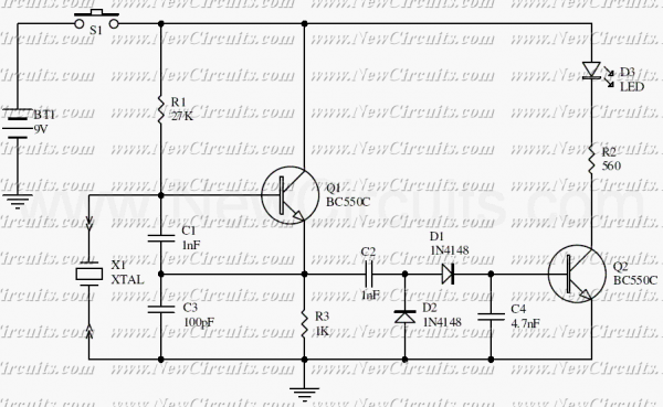
This is a simple XTal tester circuit. T1 and XTal have formed an oscillator. C1 and C2 are voltage divider for oscillator. if the XTal is safe, the oscillator will work well and its output voltage will be rectified...
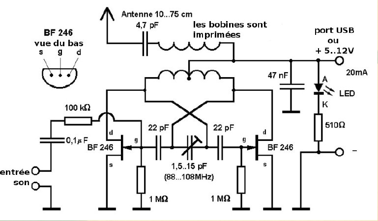
This compact FM transmitter is designed for connection to a USB port and has a range of approximately 50 meters. It can be utilized alongside multiple mini-transmitters to create a diverse and engaging radio program. The power supply through...
Op-amps have been widely used in low-frequency oscillators. Op-amps, or operational amplifiers, are versatile components frequently utilized in the design of low-frequency oscillators. These devices are capable of generating periodic waveforms, such as sine, square, or triangular waves, which are...
A compact FM transmitter designed for educational purposes. The RF section of this transmitter can be easily integrated into various projects. However, utilizing the PLL feature requires knowledge of constructing a serial data link and connecting the LPFM transmitter...
This tracking transmitter consists of four distinct subassemblies: a free-running multivibrator, a transmit switch, an audio-tone generator, and an FM transmitter. The multivibrator, which produces a pulse width with a pulse separation of 1500 ms, is built around Q1...