
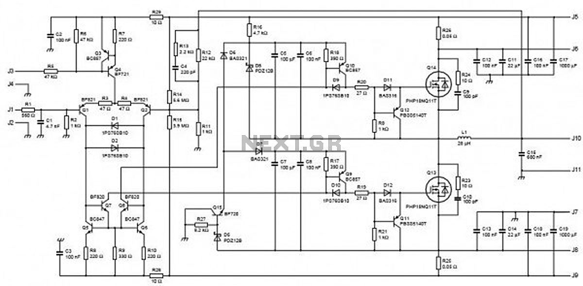
300 Watt audio Amplifier


Part List
R1-19= 1Kohm 5W R34-35= 0.1ohm 5W C14-17= 100uF 100V
R2-3= 4.7Kohm R36-43= 39ohm C15= 100nF 250V polyester
R4-5= 22ohm R37-42= 5.6Kohm 1W Q1-2-3= BC547
R6-14= 10Kohm R38-41= 220ohm 5W Q4-5-6= BC557
R7-8= 1Kohm R39-40= 0.1ohm 5W Q7-11-12= BD140 or BC640
R9-23*=10K ohm R44-45= 0.1ohm 5W Q8= BC549
R10= 10ohm *see circuit sch. R46= 4.7ohm 2W Q9-10-15= BD139 or BC639
R11-13= 2.2Kohm R47= 100ohm Q13-14= MJ15004
R12= 22Kohm C1= 2.2uF 25V Q16-17= MJ15003
R15-16= 22ohm C2-6= 330pF ceramic TR1= 2K2 Trimmer
R17-18= 4.7Kohm C3-8= 100uF 100V F1-2= 5A Fuse Fast
R20-25= 390ohm C4-9= 100nF 250V D1-3= 5.1V 0.5W Zener
R21= 6.8Kohm C5= 100nF 100V polyester D2= 62V/5W Zener or 47V and 15V in series
R22= 4.7Kohm C7= 100uF 25V D4-5= 1N4004
R24-26-33= 220ohm C10= 1.5nF 100V polyester L1=10 turns diameter 1mm in 15mm diameter tube
R27-32= 100ohm 1W C11-12= 1.5nF 100V polyester
R28,29,30,31= 100ohm C13-16= 100nF 250V polyester *Use R23=6k8 for 4 ohm loudspeakers.
SPECIFICATIONS
POWER OUTPUT 200W rms/8 ohm
310W rms/4 ohm
800W rms/8 ohm (Bridge mode)
FREQUENCY RESPONSE 20HZ-20KHZ +/-0.5dB
INPUT SENSITIVITY 1V for 200W/300W
HUM AND NOISE -105dB
THD <0.1%
DAMPING FACTOR 65
Power Supply For 300W Amp.
OUT VOLTAGE FROM POWER SUPPLY
[+V1]= +68V DC [+V2]= +15V DC [+V3]= +68V DC
[-V1]= -68V DC [-V2]= -15V DC [-V3]= -68V DC
Power Supply for two Power channels, with Protection and Bridge circuit (soft start).
T1= 230V AC/ 2X47V 350VA
2X15V 30 VA*
C1-4= 4700 uF 100V C15= 33nF 630Vac
C5-8= 4700 uF 25V CX= 33nF 630Vac
T2= 230V AC/ 2X47V 350VA C6-9= 100nF 100V F1= Fuse 2A Slow
BR1-3=4x1N5404 or 35A Bridge C7-10= 47uF 25V IC1= 7815T
RX= 47R 15W C11...14= 4700uF 100V IC2= 7915T
The described power amplifier circuit is designed for high output applications, capable of delivering substantial power to speakers with varying impedance. The input stage employs a complementary differential configuration with transistors Q1 to Q5, providing initial signal amplification and stability through the use of emitter resistors. The output stage, consisting of transistors Q10, Q11, Q13, Q14, and Q16 to Q17, further amplifies the signal with a gain set by resistors R28, R29, and R44. The thermal sensing-bias transistor Q8 plays a crucial role in maintaining the quiescent current, ensuring optimal performance and preventing overheating.
Protection mechanisms are integrated through transistors Q12 and Q15, which monitor the output conditions and safeguard the output transistors from excessive current and voltage. The frequency response of the amplifier is finely tuned using capacitors, ensuring a wide bandwidth suitable for audio applications. The power supply section is designed to provide the necessary voltages for both the amplifier and any additional circuits, utilizing a robust transformer and filtering capacitors to maintain stable operation under load.
This amplifier is suitable for applications requiring high power output and fidelity, making it ideal for professional audio systems, outdoor sound installations, and high-efficiency speaker systems. The detailed component list allows for accurate assembly and troubleshooting, ensuring reliability and performance in demanding environments. For many application there's no substitute for sheer power- low efficiency speakers, outdoor sound systems, or maybe you like the full flavour of the dynamic range of a high power amp. Whatever your requirement-this super power module should fit the bill. How it works: The amplifier can be divided into three separate parts. These are : the input stage, which consists of Q1-Q9 , a high gain, low power driver; the output or power stage- witch only has a voltage gain of four but enormous power gain; and the power supply.
The input stage is a complementary -differential network, each ''side'' with its own current source. Each transistor in this stage is run at a collector currant of about 0.7mA. Emitter resistors are employed to stabilize the gain and improve linearity. The output of Q1-Q5 drives Q7 and Q9. The latter are virtually two constant-current sources run about 7mA collector current. With an input signal these ''current'' sources are modulated out of phase - the collector current of one decreases while the other increases. This configuration provides quite an amount of gain. In between the bases of these two transistors is Q8, the thermal sensing-bias transistor. The voltage across Q8 may be adjusted by TR1, thus setting the quiescent bias current for output stage.
The output stage, Q10-Q11, Q13-Q14 and Q16-17, has a gain of about five, set by R44 and R28 plus R29. Diodes D4 and D6 prevent reverse biasing of Q10 and Q11 (otherwise the output would be limited). Protection of the output transistors is provided by Q12 and Q15 which monitor both current and voltage in the output transistors and bypass the base current if the limit is exceeded.
Frequency stabilization provided by capacitors C6, C11, C12 and the RC networks R31/C10 plus R46/C15. Frequency response of the amplifier is set by C1 and C7 (lower limit), C6 sets the upper frequency limit.
If you want use the Protection DC and Balance/Bridge circuits. All the transistors that are inside the interrupted line are placed on an aluminium corner and he screwed on a suitable heatsink. The transistors Q7,Q10,Q11, Q8, Q9, Q13,Q14,Q16 and Q17 placed on this aluminium corner, with suitable isolation from this.[ETI 4/80] >>>>>>> Here are some more guides to using and setting up the 300W power amp.
Part List R1-19= 1Kohm 5W R34-35= 0.1ohm 5W C14-17= 100uF 100V R2-3= 4.7Kohm R36-43= 39ohm C15= 100nF 250V polyester R4-5= 22ohm R37-42= 5.6Kohm 1W Q1-2-3= BC547 R6-14= 10Kohm R38-41= 220ohm 5W Q4-5-6= BC557 R7-8= 1Kohm R39-40= 0.1ohm 5W Q7-11-12= BD140 or BC640 R9-23*=10K ohm R44-45= 0.1ohm 5W Q8= BC549 R10= 10ohm *see circuit sch. R46= 4.7ohm 2W Q9-10-15= BD139 or BC639 R11-13= 2.2Kohm R47= 100ohm Q13-14= MJ15004 R12= 22Kohm C1= 2.2uF 25V Q16-17= MJ15003 R15-16= 22ohm C2-6= 330pF ceramic TR1= 2K2 Trimmer R17-18= 4.7Kohm C3-8= 100uF 100V F1-2= 5A Fuse Fast R20-25= 390ohm C4-9= 100nF 250V D1-3= 5.1V 0.5W Zener R21= 6.8Kohm C5= 100nF 100V polyester D2= 62V/5W Zener or 47v and 15V in series R22= 4.7Kohm C7= 100uF 25V D4-5= 1N4004 R24-26-33= 220ohm C10= 1.5nF 100V polyester L1=10 turns diameter 1mm in 15mm diameter tube R27-32= 100ohm 1W C11-12= 1.5nF 100V polyester R28,29,30,31= 100ohm C13-16= 100nF 250V polyester *Use R23=6k8 for 4 ohm loudspeakers .
SPECIFICATIONS POWER OUTPUT 200W rms/8 ohm 310W rms/4 ohm 800W rms/8 ohm (Bridge mode) FREQUENCE RESPONSE 20HZ-20KHZ +/-0.5dB INPUT SENSITIVITY 1V for 200W/300W HUM AND NOISE -105dB THD <0.1% DAMPING FACTOR 65 . Power Suplly For 300W Amp. OUT VOLTAGE FROM POWER SUPPLY [+V1]= +68V DC [+V2]= +15V DC [+V3]= +68V DC [-V1]= -68V DC [-V2]= -15V DC [-V3]= -68V DC Power Supply for two Power channel , with Prodection and Bridge circuit (soft start ).
T1= 230V AC/ 2X47V 350VA ................ 2X15V 30 VA* C1-4= 4700 uF 100V C15= 33nF 630Vac C5-8= 4700 uF 25V CX= 33nF 630Vac T2=230V AC/ 2X47V 350VA C6-9= 100nF 100V F1= Fuse 2A Slow BR1-3=4x1N5404 or 35A Bridge C7-10= 47uF 25V IC1= 7815T RX= 47R 15W C11...14= 4700uF 100V IC2= 7915T 🔗 External reference
Related Circuits
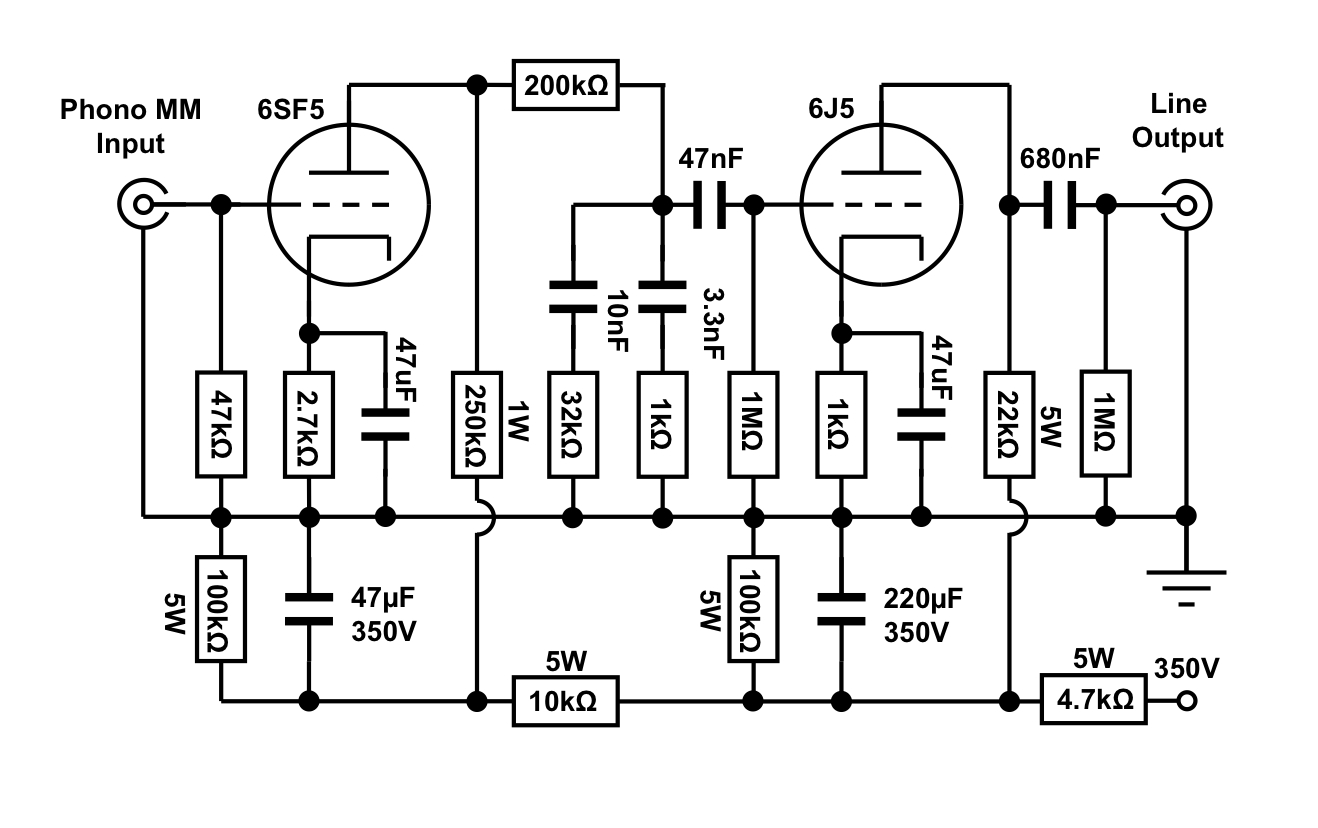
An octal preamplifier can be constructed as a standalone unit without the linestage component. However, this is not feasible due to its split RIAA configuration, which divides the RIAA equalization circuit into two sections: one following the first stage...
This circuit is capable of delivering approximately 200W of power output, produced by Phillips Semiconductor. It utilizes two PHP1BN11QT devices and operates with an input voltage range of 30 to 45 Volts DC. The described circuit is a high-power switching...
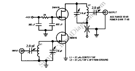
The 200 MHz JFET possesses the following characteristics: 1. Low crossmodulation 2. High large-signal handling capability 3. No requirement for neutralization 4. Automatic Gain Control (AGC) managed by adjusting the biasing of the upper. The 200 MHz Junction Field Effect...
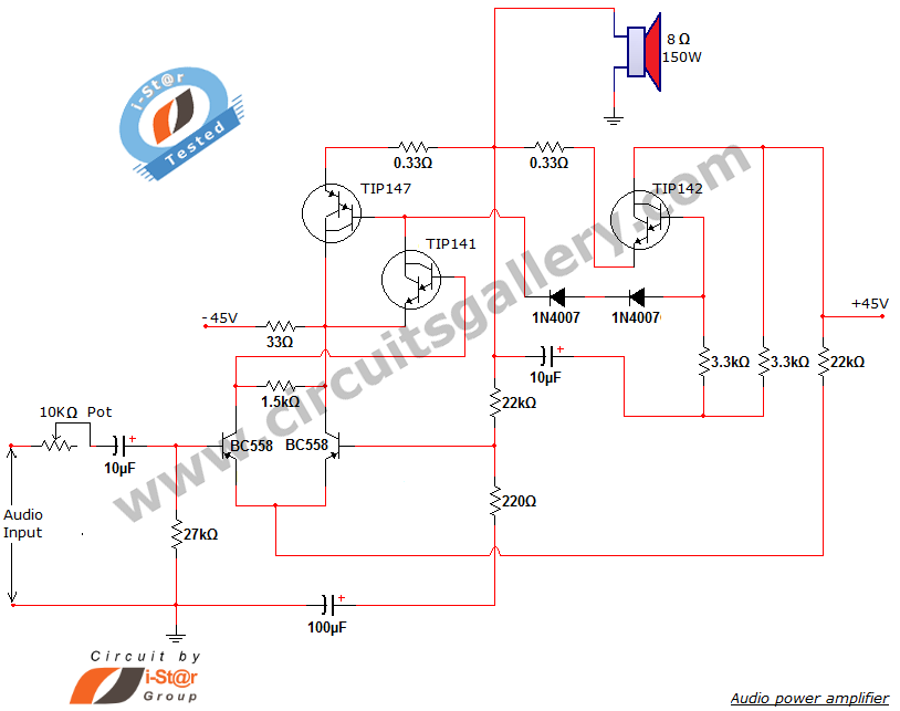
This document presents a new audio power amplifier schematic utilizing TIP darlington pair transistors. It is suitable for both home audio and car audio amplifiers. The TIP142 and TIP147 darlington pair transistors create a push-pull high-power amplifier configuration, while...
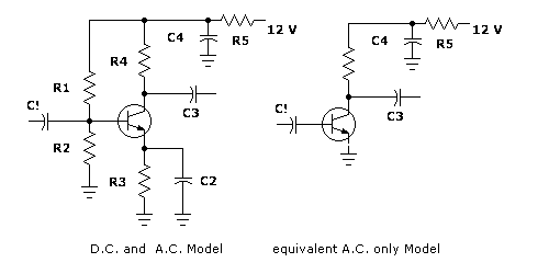
Feedback - This is where part of the output signal is fedback to the input BUT 180° out-of-phase (i.e. partially cancels the input). If it were in-phase feedback then we would have an oscillator - which in this case...
This project involves the construction of a VHF-UHF linear amplifier capable of operating at frequencies ranging from 47 MHz to 740 MHz. It serves as the final output stage for any transmitter functioning within these frequencies. The amplifier utilizes...