
300HZ - 3KHZ Audio Filter

The circuit described operates within the critical frequency range for human speech, employing a band-pass filter configuration that effectively isolates the desired frequencies while eliminating unwanted noise. The use of integrated circuits (ICs) such as the TL072 is crucial, as they provide high input impedance and low output noise, which are essential for preserving the integrity of the audio signal.
The filter design consists of two sections: the first section, implemented with IC1A, acts as a high-pass filter. It utilizes a resistor-capacitor (RC) network to block frequencies below 300Hz, allowing only higher frequencies to pass through. The choice of a 120kΩ resistor (R1) in conjunction with a 2.2nF capacitor (C1) establishes the cutoff frequency, ensuring effective attenuation of low-frequency noise.
The second section, implemented with IC1B, is a low-pass filter designed to cut off frequencies above 3kHz. This section features a 150kΩ resistor (R2) and a 150pF capacitor (C3), which together set the upper cutoff frequency, thus preventing high-frequency signals from interfering with the clarity of the speech signal.
The remaining resistors and capacitors in the circuit, including R3 through R8, and C4 through C12, provide additional stability and performance enhancements. For instance, the use of 1/4W, 1-2% tolerance resistors ensures that the circuit maintains its performance characteristics over a range of operating conditions.
Overall, this circuit is an effective solution for applications requiring clear speech transmission, such as in telecommunications and audio processing systems. The design emphasizes precision components and careful attention to frequency response, ensuring that the critical speech frequencies are preserved while eliminating extraneous noise.The human speech apprehend a small area of frequencies, that is extended from 300HZ until 3KHZ. This spectrum is also internationally recognized for the transmission of speech via telecommunications networks. This is also the mainer use of this circuit, one and it can be used in uses that we needed this concrete spectrum of frequencies, rejecting the spectrum on and under what, making comprehensible the speech.
The circuit is constituted by two active units, filters of second class (calculated for critical damping). The first filter round the IC1A rejects the low frequencies (under 300 HZ) [high pass] and the second IC1B high (above 3KHZ) [low pass], composing thus a total filter band pass of area (300HZ-3kHZ).
In order to has good yield the filter, as with all the filters, it should are used resistances metal film 1% and capacitors polysteryne. Part List R1= 120Kohm R7= 150Kohm C6= 100nF 100V polystyrene R2= 100Kohm R8= 47Kohm C7= 560pF R3= 470Kohm C1-2-8= 2.2nF 100V polystyrene C11= 150pF R4-7= 8.2Kohm C3= 150pF C12= 10uF 25V R5= 6.8Kohm C4-9= 100nF 100V IC1= TL072 R6= 33Kohm C5-10= 47uF 25V All resistors is 1/4W 1-2% 🔗 External reference
Related Circuits
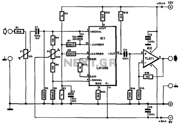
Often, the frequency of a signal must be doubled, and the modulator/demodulator chip LM1496 serves as an ideal basis for this application. From trigonometry, it is well known that 2sin(x)cos(x) = sin(2x) and sin^2(x) = 1 - cos^2(x). These...
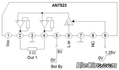
The third series of the function utilizes the same system, specifically BTL (Bridge Transformer Less). This configuration offers several advantages, including the elimination of coupling capacitors and coupling transformers. The BTL (Bridge Transformer Less) configuration is a significant advancement in...
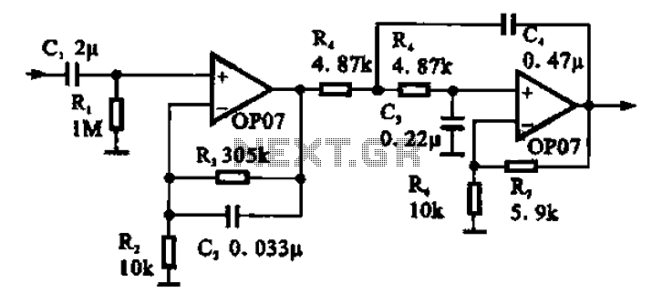
Broadband 0.1 to 10 Hz filter amplifier. The broadband circuit consists of two operational amplifiers configured as filter amplifiers operating in the frequency range of 0.1 to 10 Hz. The broadband filter amplifier circuit utilizes two operational amplifiers (op-amps) to...
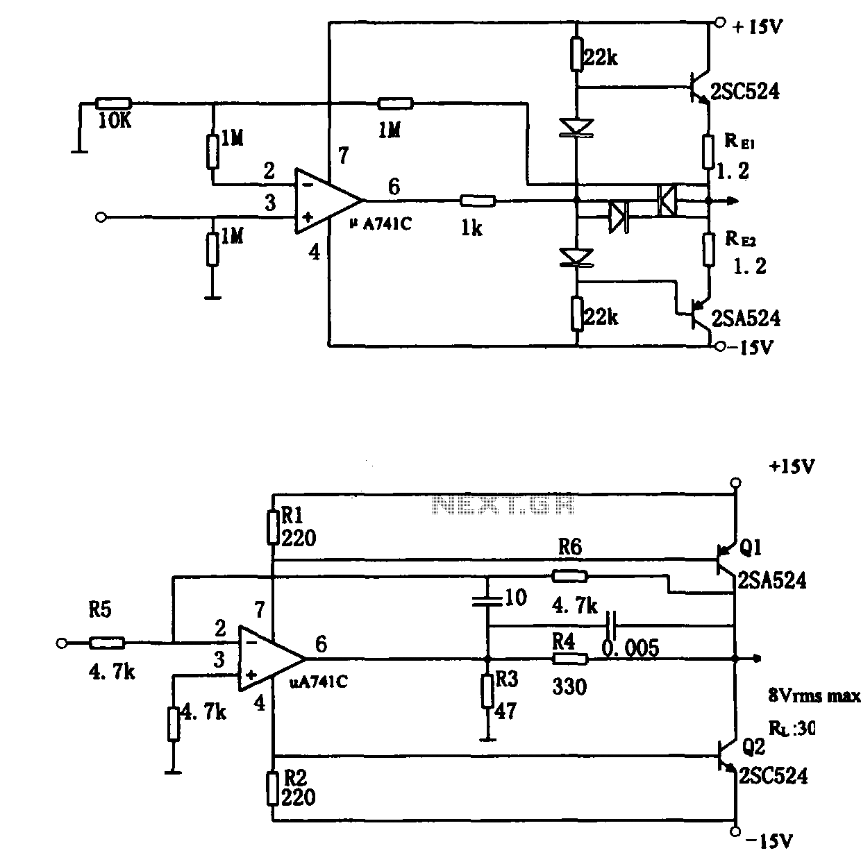
The direct coupling audio power amplifier utilizes an integrated operational amplifier. There are typically two practical configurations. The first configuration, depicted in (a), features a circuit structure that includes the output of the operational amplifier and a complementary symmetry...
.gif)
This circuit utilizes a single integrated circuit (IC) along with a minimal number of external components to display audio levels through ten LEDs. The input voltage range is from 12V to 20V, with a recommendation for 12V. The LM3915...
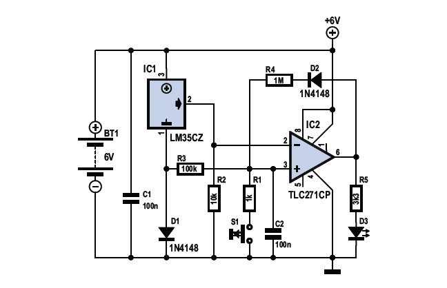
To determine whether it is freezing, one needs to measure the temperature accurately. This requires a reliable temperature sensor. The LM35CZ sensor, which operates within a range of -40 to 110 °C, is suitable for this purpose. It is...