
300m fm transmitter circuit design project

This FM transmitter circuit operates efficiently at a low voltage of 3 volts and is designed for simplicity and ease of assembly. The core component of the circuit is the oscillator, which generates the FM signal. The oscillator is typically built around a transistor that amplifies the oscillations produced by the LC circuit formed by the inductor (coil) and the capacitor. The inductance of the coil and the capacitance of the capacitor determine the frequency of the oscillation, which can be adjusted to any frequency within the FM band.
To ensure optimal performance, it is crucial to maintain a proper distance between the coils after soldering. This prevents unwanted coupling that can lead to instability in the frequency output. The option to use a fixed capacitor allows for basic functionality, but the inclusion of a variable capacitor provides enhanced tuning capabilities, allowing the user to fine-tune the frequency more accurately.
The circuit's effective range of approximately 300 meters in open air makes it suitable for various applications, such as low-power broadcasting or personal projects. For optimal transmission, an appropriate antenna must be connected to the aerial point. The length of the antenna is critical; at a frequency of 100 MHz, a half-wavelength antenna should measure 150 cm, while a quarter-wavelength antenna should measure 75 cm. The antenna's length affects the efficiency of the signal transmission, and adjustments may be needed based on the specific environment in which the transmitter operates.
Overall, this FM transmitter circuit serves as a practical example of basic RF (radio frequency) design principles, providing a foundation for further exploration into wireless communication technologies.This fm transmitter circuit is very simple and it has a acceptable transmission. The signal transited from this fm transmitter circuit can be received at almost 300 meters in open air. The circuit require a 3volts operating voltage and can be tuned anywhere in the FM band. After the coil in soldered into place spread the coils apart about 0. 5 to 1mm so that they are not touching. If you don`t have a trim cap you can use a fixed value capacitor and you can vary the TX frequency by adjusting the spacing of the coils or placing a small piece of ferrite inside the coil, but the better way to change the transmission frequency is to use a variable capacitor. Connect a half or quarter wavelength antenna (length of wire) to the aerial point. At an FM frequency of 100 MHz these lengths are 150 cm and 75 cm respectively. 🔗 External reference
Related Circuits
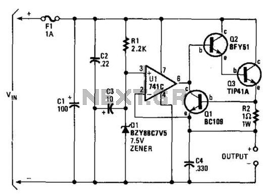
A regulator enables the powering of a 7.5-V cassette recorder or other devices from a 12-V DC automotive system. The circuit can provide approximately 600 mA of current. Q3 requires a heatsink due to its potential to dissipate up...
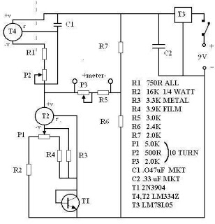
There are many digital thermometers with ±1°C displays, but their accuracy is approximately ±1°C and they cannot be calibrated. A thermometer circuit was created using components available at a local electronics hobby shop, providing an educational experience. For a...
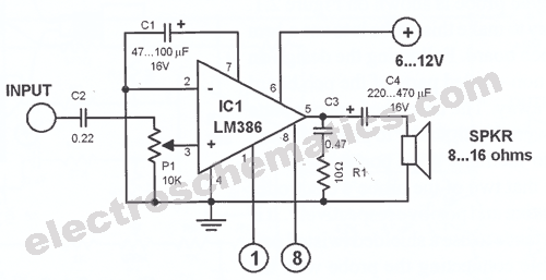
This car stereo booster utilizes an LM2896 integrated circuit, which features two amplifiers. It operates with supply voltages ranging from 3 to 15 volts. The power output is 2.5 watts per channel when connected to an 8-ohm load at...
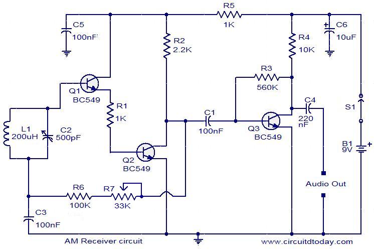
Circuit diagram of a modulator circuit in a transmitter and receiver of amplitude modulation. The modulator circuit in an amplitude modulation (AM) transmitter and receiver plays a crucial role in the process of encoding information onto a carrier wave. In...
A program is available to control a simple servo motor in both directions. This program has been tested and can be shared for others to benefit from it. It allows the servo motor to rotate in both clockwise and...
Circuit Magic is an electrical circuits simulation program specifically designed for students teaching basics electronics, electrical laws & circuit theory. Unlike many electronic circuit analyzers, Circuit Magic can analyze circuits like a man. Circuits are simulated step by step,...