
LM2896 Car Audio Amplifier Circuit

The car stereo booster circuit is built around the LM2896 IC, which is a dual power amplifier designed for automotive audio applications. The circuit is capable of operating efficiently within a voltage range of 3 to 15 volts, making it versatile for various automotive power systems. The output power specifications indicate that the circuit can deliver 2.5 watts per channel under normal conditions with an 8-ohm load, which is suitable for typical car speakers.
When configured in a bridge mode, the circuit can provide a higher output power of 9 watts, which significantly enhances audio performance and volume levels. This bridge configuration allows for the utilization of both amplifiers within the LM2896 to drive a single speaker effectively, maximizing sound output without the need for additional components.
The choice of load impedance is critical; the circuit can accommodate both 4-ohm and 8-ohm speakers. The output power is contingent upon the supply voltage and the impedance of the connected load. For instance, at a supply voltage of 12 volts with a 4-ohm load, the circuit draws a maximum current of 1 ampere, which must be considered in the overall power supply design to ensure reliable operation without overloading the power source.
The inclusion of capacitor Cx and resistor Rx in the circuit is essential for stability and performance enhancement. These components aid in filtering and signal conditioning, ensuring that the audio output remains clear and distortion-free. The design of the printed circuit board incorporates specific provisions for these components, ensuring ease of assembly and reliability in the final product.
For stereo applications, it is recommended to construct an identical second amplifier circuit. This allows for true stereo sound by driving a second speaker, effectively utilizing both channels of the LM2896. Proper wiring and configuration will ensure that the audio experience in the vehicle is immersive and high-quality, meeting the demands of modern audio systems.This car stereo booster uses an LM2896 IC which has two integrated amplifiers. It can be powered with voltages up to 15 volts. The power output is 2. 5 watts per channel with an 8 © load and supply voltage of 12 volts. Using the bridge tehnique in the circuit gives a power output of 9 watts. The car audio booster can be powered up from 3 up to 15 volts. The load impedance that can be connected at its output can be either 4 © or 8 ©. The supply voltage and the load impedance influence the output power level. This amplifier circuit is designed as a booster for auto radio/cassette players. The current consumption by maximum power output and a 4 © load is 1 ampere. Add the additional capacitor Cx and the resistor Rx to the circuit as shown by the dashed lines in the schematic diagram. These parts were considered during the design phase of the printed circuit and appropriate holes, and soldering points are already available on the circuit board.
Instead of using 2 speakers, use a single speaker. Connect the speaker to both output lines of the amplifier as shown by the dashed lines in the booster schematic diagram. You can use either 4 © or 8 © speaker. Now, since only a single speaker is connected to the amplifier circuit, you must construct a second amplifier circuit identical to this one if you want a stereo system.
The second circuit will work for the second channel. 🔗 External reference
Related Circuits
The circuit automatically lights a bulb upon the arrival of a telephone ring and simultaneously mutes the audio from the music system or TV while the telephone handset is off-hook. The lighting of the bulb not only indicates an...
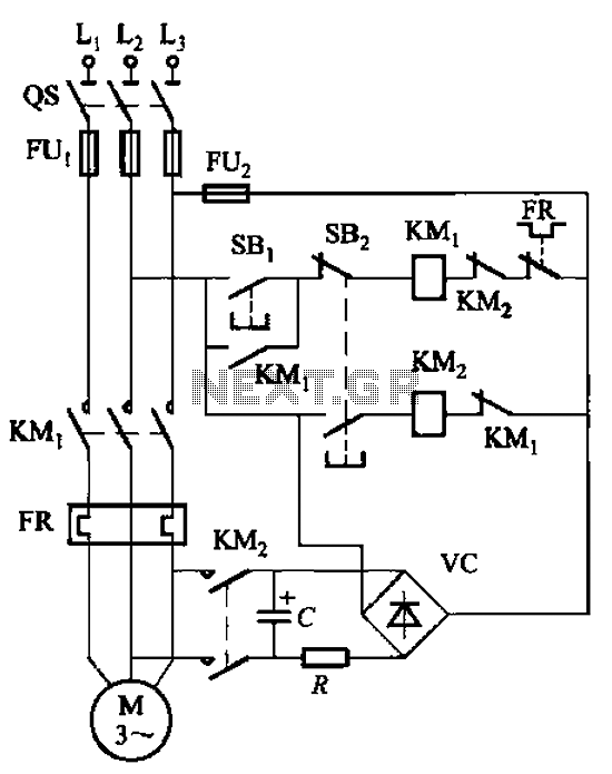
The circuit depicted in Figure 3-138 utilizes the principle of energy storage through capacitor discharge to achieve braking. The capacitance (C) and resistance (R) parameters are determined based on the size of the motor power. The capacitance (C) is...
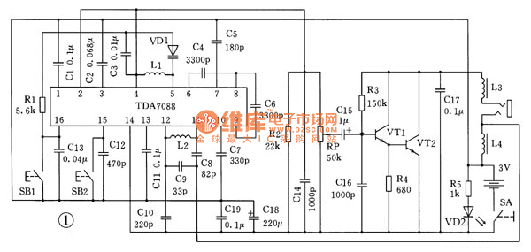
This is the schematic diagram for an automatic search FM radio. The primary component is the TDA7088 integrated circuit, which encompasses the FM radio receiver, antenna, oscillator, mixer, automatic frequency control (AFC) circuit, intermediate frequency amplifier (with an IF...
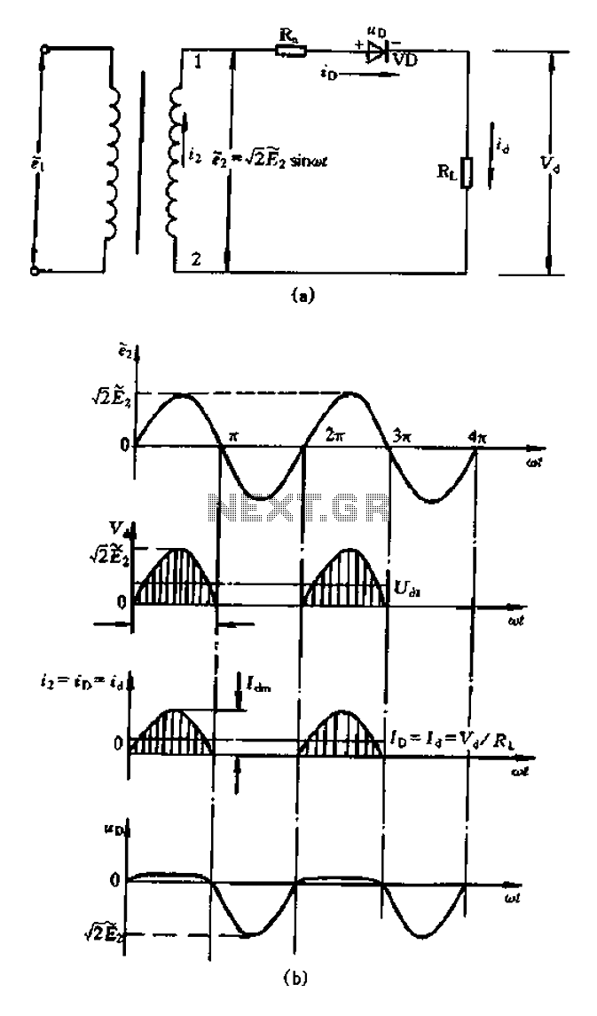
A bridge rectifier capacitor filter serves as a primary power supply for current amplifier circuits. This power supply configuration is straightforward and offers enhanced performance. The bridge rectifier circuit is a full-wave rectifying circuit, meaning it converts both the...
During rainy seasons, it can be quite bothersome when the car wipers operate continuously without pause. Have you ever considered implementing speed control for the wipers? While there are wiper control modules available commercially, many of them can be...
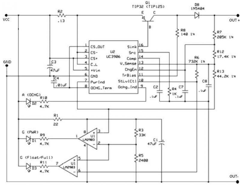
The UC3906 battery charger circuit controller includes all necessary circuitry to manage the charge and hold cycles for sealed lead-acid batteries. This circuit is specifically designed to deliver the appropriate charging voltage and current based on the battery's temperature...