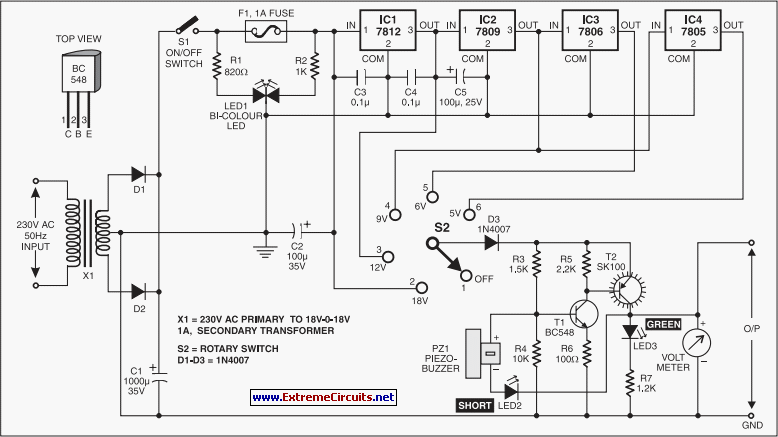
servo motor tester circuit
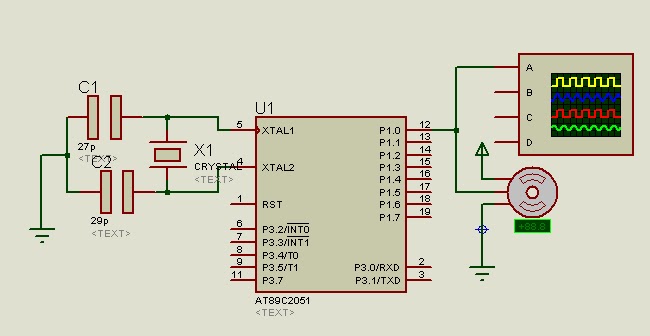
A program is available to control a simple servo motor in both directions. This program has been tested and can be shared for others to benefit from it. It allows the servo motor to rotate in both clockwise and counterclockwise directions, and it can be modified according to individual requirements and preferences.
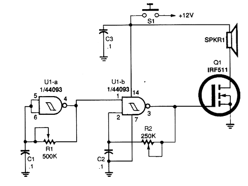
The circuit for controlling a servo motor typically consists of a microcontroller, a power supply, and the servo motor itself. The microcontroller generates a PWM (Pulse Width Modulation) signal that determines the position of the servo motor. The PWM signal is sent to the control wire of the servo, which interprets the signal and adjusts its position accordingly.
In this setup, a common microcontroller such as an Arduino can be utilized. The Arduino outputs a PWM signal on one of its digital pins, which is connected to the signal wire of the servo. The ground pins of both the Arduino and the servo must be connected to a common ground to ensure proper operation.
The power supply should match the voltage requirement of the servo motor, which is typically between 4.8V and 6V for standard servos. It is essential to ensure that the power supply can provide sufficient current, as servos can draw significant current, especially under load.
The program can be written in the Arduino IDE, where the servo library simplifies controlling the motor. The library provides functions to set the angle of the servo motor, allowing for easy manipulation of its position. By adjusting the duration of the high signal in the PWM, the angle of rotation can be controlled, enabling the servo to move in both clockwise and counterclockwise directions.
Overall, this circuit design provides a straightforward approach to controlling a servo motor, making it suitable for various applications, including robotics, automation, and hobby projects. The flexibility to modify the program allows users to tailor the functionality to their specific needs.Here is the program to control simple servo motor in both direction. I test it today and think that i should also share it with you people so that you can also enjoy and can takebenefit. This program will rotate servo motor in both clock wise and anti clock wise direction you can modify it according to your requirement and according to your wish a
s suite to you. 🔗 External reference

