
300W inverter power 24Vdc to 220Vac by MJ15003CA3130CD4027

The 300W inverter circuit converts a 24V DC input from a battery into a 220V AC output suitable for powering various household appliances. The core of the inverter relies on the CD4027 dual JK flip-flop, which is used to generate the necessary square wave signal that drives the power transistors. This square wave is essential for creating the alternating current (AC) output.
The NE555 timer is configured in astable mode to provide a timing pulse that controls the frequency of the output waveform. By adjusting the resistors and capacitors connected to the NE555, the frequency can be tuned to achieve the desired output of 50Hz.
The CA3130 operational amplifier is utilized for signal conditioning and amplification. It enhances the performance of the circuit by providing a stable reference voltage and ensuring that the output waveform remains consistent and free from distortion.
To regulate the voltage supply for the control circuitry, the LM7805 voltage regulator is employed. It steps down the voltage to a stable 5V, which is required by the logic components of the inverter.
The power stage of the inverter typically consists of transistors or MOSFETs that switch the DC input on and off rapidly, creating the necessary AC waveform at the output. Adequate heat sinking and protection mechanisms should be implemented to ensure reliable operation under load conditions.
Overall, this inverter design is capable of efficiently converting low-voltage DC power into standard household AC power, making it suitable for various applications, including backup power systems and portable power supplies. Proper consideration of component ratings and thermal management will enhance the longevity and performance of the inverter circuit.This is circuit 300W Inverter power,so input battery 24V to Output 220Vac 50Hz 300W. I used main Component IC CD4027 , NE555,CA3130 and LM7805. The transistor.. 🔗 External reference
Related Circuits
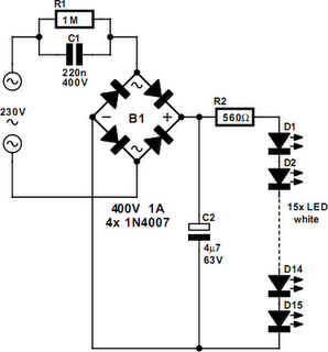
An array of white LEDs can serve as a compact lamp for living spaces. These LED lamps are commercially available and resemble standard halogen lamps, fitting into typical 230-V light fixtures. Upon inspection, it is evident that a capacitor...
The typical home solar power system primarily comprises a roof-mounted solar panel, a charge controller, and a storage battery bank, along with direct or electric connections. A home solar power system is designed to harness solar energy for residential use,...
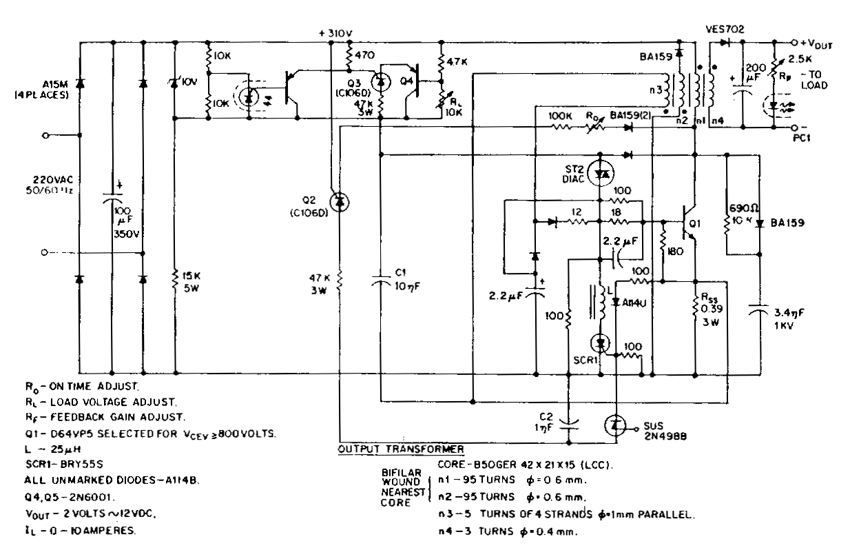
This low-voltage, high-current output switching power supply operates from a 220 VAC input. In this circuit, an ST2 diac relaxation oscillator, along with Q3, C1, and the diac, initiates the conduction of the output switching transistor Q1. The on-time...
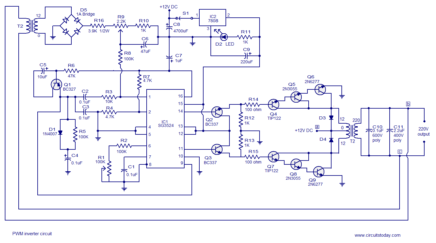
A simple PWM inverter circuit utilizes the SG3524 integrated circuit. This PWM inverter is designed for a 12V input, providing a 220V output with a maximum output power of 250 watts. The output power can be extended further. The described...
This circuit is a modified version of a function-generator circuit. It features a battery-powered sine wave generator that can be continuously adjusted from 100 Hz to 10 kHz. The described circuit utilizes a sine wave generator to produce a continuous...

The simple transistor tester in Figure 1 allows for the identification of the type of transistor and aids in detecting the emitter, collector, and base of the transistor. The simple transistor tester circuit is designed to facilitate the identification of...