
Battery-Powered Sine Generator Covers 100 Hz To 10 kHz

The described circuit utilizes a sine wave generator to produce a continuous oscillating signal. The key components typically involved in such a circuit include operational amplifiers, resistors, capacitors, and a power source.
The operational amplifier (op-amp) is configured in a feedback loop, which allows the circuit to generate a sine wave output. The frequency of the sine wave is determined by the values of the resistors and capacitors connected to the op-amp. By adjusting these component values, the frequency can be varied smoothly across the specified range of 100 Hz to 10 kHz.
The use of a battery power supply ensures portability and ease of use in various applications where access to mains power may be limited. Additionally, the circuit may include features such as a variable resistor (potentiometer) to fine-tune the frequency output, as well as output terminals for connecting to external devices or measurement equipment.
This circuit can be employed in various applications, including signal testing, audio synthesis, and research projects requiring a stable sine wave signal. The design's flexibility in frequency adjustment makes it suitable for a wide range of experimental and practical uses in electronics.This circuit, a modification of a function-generator circuit, comprises a battery-powered sinewave generator that is continuously adjustable from 100 Hz to 10 kHz 🔗 External reference
Related Circuits
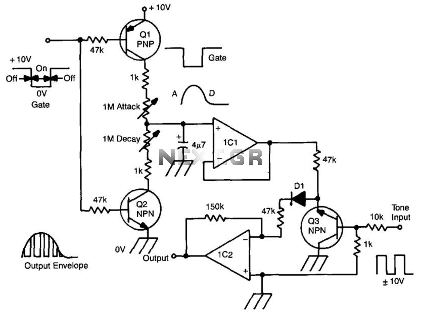
A gate voltage is applied to initiate the process. When the gate voltage is in the ON state, Q1 is activated, and capacitor C is charged through the attack potentiometer in series with the 1 kΩ resistor. By adjusting...
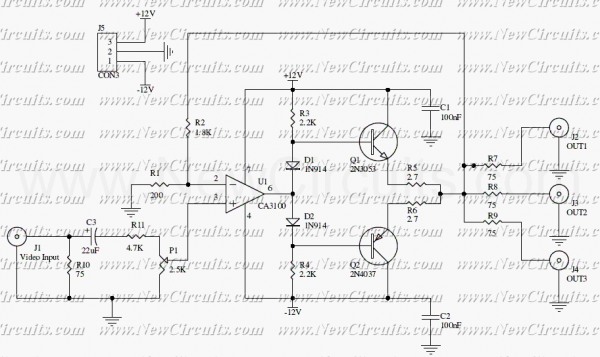
This circuit is useful to amplify and distribute video signals with low noise and without losses. The CA3100 is a fast opamp designed to amplify video signals. Set the P1 to control the input signal level to have a...
This circuit is quite effective for testing or operating counters and stepping relays, as it eliminates the need for manually setting a switch for the desired number of pulses. By pressing the appropriate switches S1 to S9, one can...
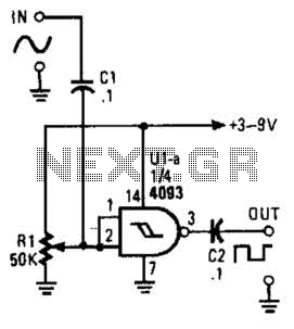
This circuit converts a sine wave into a square wave. It consists of a single 2-input NAND Schmitt trigger configured as an inverter, with an adjustable trigger level at its input. As the input voltage exceeds the gate's trigger...
A 40kHz ultrasonic transmitter circuit consists of three oscillators (F1, F2, and F3), with F3 generating a 40kHz square wave output. The frequency is primarily determined by components C1, R1, and an adjustable resistor (RP). The excitation output from...
Join the forum discussion on this post. This is a simple home telephone ringtone generator circuit built using only a few electronic components. It generates a simulated telephone ringtone and requires only a DC supply. The home telephone ringtone generator...