
frequency conversion circuit composed of TC4013

The electronic circuit operates by taking a low-frequency input signal and transforming it into a higher voltage output. The TC4013, a dual D-type flip-flop, is configured in a monostable mode, which means that it produces a single output pulse in response to a triggering input. The input pulse width of 100 µs is critical for ensuring that the circuit operates correctly, as it determines the duration for which the output voltage is generated.
When the input signal is applied, the TC4013 detects the rising edge of the pulse. If the input voltage at the comparator A1 is lower than the reference voltage UR, the comparator outputs a high signal, which activates the transistor VT1. This transistor acts as a switch, allowing current to flow through the load connected to the output, thus generating a voltage that can range from 0 to 10 V depending on the circuit design and load characteristics.
The circuit is designed to switch states quickly, with the transistor VT1 being turned on only for the duration of the input pulse (100 µs). After this time, the TC4013 resets, and the transistor returns to its off state, stopping the output voltage. This precise timing allows for effective control of the output voltage in applications where pulse-width modulation or frequency-to-voltage conversion is required. The overall design ensures that the circuit remains responsive to input frequency changes while maintaining the desired output characteristics.It can switch 0-100Hz input frequency to 0 -l0V output voltage. In the circuit, TC4013 is a monostable multivibrator, which could shape and amplify input pulse, and the input pulse width is 1OO?s. TC4013 could trigger VTl to turn on, when the input voltage of of comparator Al UQ
Related Circuits
This power supply was designed for use with the Simple hybrid amplifier published elsewhere in this issue. It is suitable for various applications as well. A cascade generator is utilized for the 170 V output, a switch-mode supply provides...

The following circuit illustrates a 2000W Power Amplifier Circuit Diagram. This circuit utilizes the BC560C transistor. Features include a robust design. The 2000W power amplifier circuit is designed to deliver high output power suitable for various applications, including audio amplification...

This is a simple basic design of a servo motor controller with a pulse generator. It utilizes the CMOS IC 7555 in astable mode to generate pulses for driving the motor. The servo motor controller circuit employs the CMOS IC...

The circuit utilizes a KD-9300 music IC, which activates when the button switch (SB) is pressed, causing the electric lamp (E) to light up for approximately 20 seconds before automatically turning off. The setup includes a half-wave rectifier and...

Emits a beep if the door remains open for more than 20 seconds. This circuit is housed in a compact enclosure and is positioned in the refrigerator near the lamp or the opening. The described circuit functions as a door...
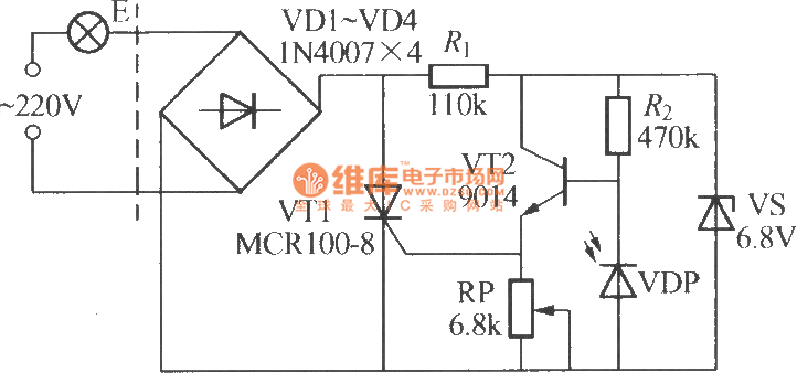
The VDP is a photodiode that exhibits low resistance during the day, approximately 1 kΩ. As a result, transistor VT2 remains off, which keeps thyristor VT1 in the off-state due to the absence of trigger current at the gate,...