
Motor Bike Headlight Controller Circuit

The motorcycle headlight controller circuit is designed to enhance safety and convenience by ensuring that the headlight operates automatically based on the conditions of the motorcycle's battery charge. This system functions independently of the traditional light and ignition switches, allowing for automatic operation when the motorcycle is in use.
The circuit typically begins with a voltage sensing mechanism that monitors the battery's charge level. When the battery voltage exceeds a predetermined threshold, the controller activates the headlight. Conversely, if the battery voltage drops below this threshold, the circuit will automatically turn off the headlight to conserve battery power. This feature is particularly beneficial in preventing battery drain when the motorcycle is not in use.
The main components of the circuit include a microcontroller or comparator circuit, a relay for switching the headlight on and off, and a voltage divider to monitor the battery voltage. The microcontroller can be programmed to adjust the sensitivity of the voltage detection, allowing customization based on the specific battery type and motorcycle model.
In addition to the basic functionality, the circuit may also incorporate features such as a delay mechanism that prevents the headlight from turning off immediately when the motorcycle is turned off, allowing for a graceful shutdown. Furthermore, the inclusion of an LED indicator can provide visual feedback regarding the operational status of the headlight controller.
Overall, the motorcycle headlight controller circuit serves as an effective solution for enhancing the reliability and safety of motorcycle lighting systems by automating headlight operation based on battery conditions.Motor Bike Headlight Controller Circuit Circuit This circuit automatically turns a motor cycle`s headlight on and off, independently of both the light and ignition switches, provided the battery is fully charged. The first stage.. 🔗 External reference
Related Circuits
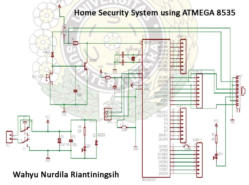
The Atmega 8535 Color Conversion to Frequency project utilizes instrumentation technology to recognize colors, also known as a color sensor, which is essential in various industrial applications. This sensor has multiple uses, ranging from the paint industry to satellite...
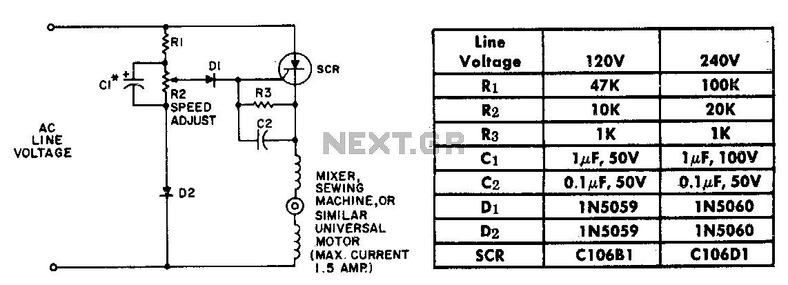
The resistor-capacitor network R1-R2-C1 generates a ramp-type reference voltage that is superimposed on an adjustable DC voltage controlled by the speed-setting potentiometer R2. This reference voltage, available at the wiper of R2, is compared against the residual counter electromotive...
This is an electric thermometer circuit composed of the LM134. In the circuit, the voltage or current output by the LM134 is proportional to the thermodynamic temperature, which can be read on a 100 µA meter. The test temperature...

This board layout was created using the SOIC version of a PIC16F627A without drawing the usual schematic first. Most of the part values are etched on the Layout. The SIP resistor packs I used are 10k ohm, some experimentation...
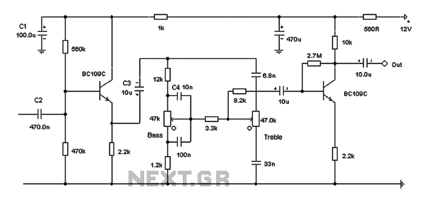
Based on the classic Baxendall tone control circuit, this design offers a maximum cut and boost of approximately 10 dB at 10 kHz and 50 Hz. Since the controls are passive, the final transistor provides a slight boost. The...
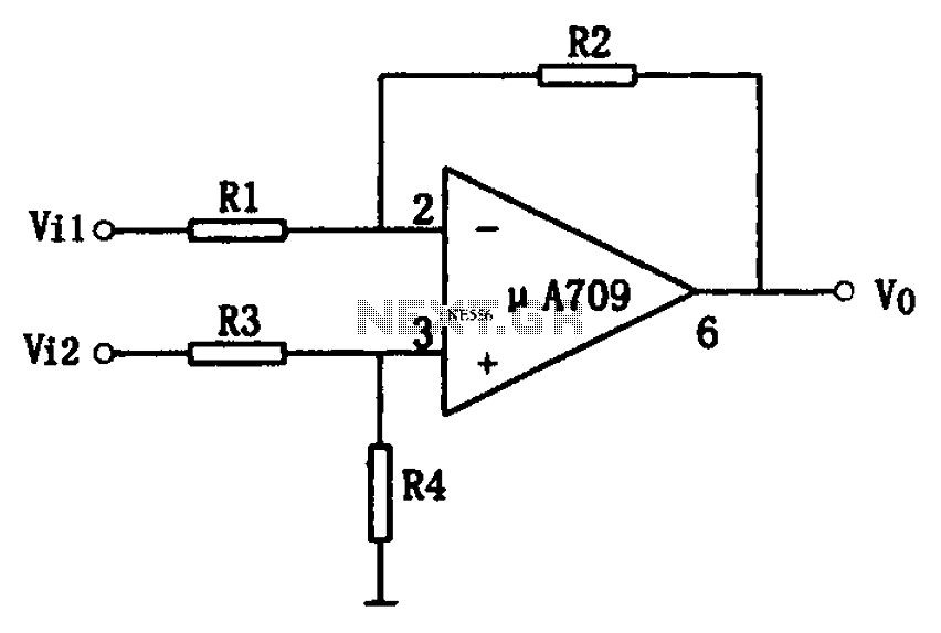
The simple differential amplifier circuit consists of two input signals, Vi1 and Vi2, which are connected through resistors R1, R3, and R4, forming a voltage divider circuit at the op-amp input. Vi1 is applied to the inverting input of...