
35W resistive and capacitive half-wave phase-shift trigger doer control circuit

The 35W resistive and capacitive half-wave phase-shift trigger control circuit is an essential component in welding applications where precision and stability are crucial. The circuit operates by integrating a 35W DC servo motor, which provides the necessary torque and responsiveness for effective wire feeding and welding carriage movement. The use of potentiometers RPi and RPz allows for fine-tuning of the input parameters, enabling the operator to adjust the sensitivity and response of the circuit according to the welding conditions.
The voltage divider, consisting of RP4, plays a critical role in feedback regulation. By extracting a portion of the feedback voltage, RP4 ensures that the circuit can dynamically adjust to variations in load and other operational conditions. This feedback is superimposed on the AC voltage, creating a phase shift that is vital for maintaining the desired operational characteristics of the motor. The resistive and capacitive components work together to create a robust negative feedback loop, which is essential for achieving stable speed control during welding operations.
Furthermore, the adjustment of RP3 directly influences the armature voltage supplied to the servo motor. By varying this voltage, the circuit can modulate the speed of the motor, allowing for precise control over the welding process. This capability is particularly beneficial in applications that require different welding speeds for various materials or thicknesses, ensuring optimal performance and weld quality.
Overall, this control circuit exemplifies a sophisticated approach to managing the dynamics of welding equipment, leveraging phase-shifting techniques and feedback mechanisms to enhance operational efficiency and effectiveness.35W resistive and capacitive half-wave phase-shift trigger doer control circuit Automatic or semi-automatic welding equipment in order to control the wire feeding, welding car travel, requires the use of drive control circuit to meet the requirements of the welding process. (1) 35W blocking off half-wave phase-shift trigger drag the control circuit circuit is shown. Motor using 35W DC servo motor. By the potentiometer RPi, RPz and voltage divider consisting of RP4, RP4 is removed from the feedback voltage, superimposed on the AC voltage resistive and capacitive phase-shifting, to form a strong negative anti fed, stable speed control purposes. Adjust RP3, change the armature voltage, to achieve speed control purposes.
Related Circuits
A long time ago, when telephones were simple and reliable from an electrical standpoint, telecom operators installed surge protection on all telephone lines at risk from storms. Paradoxically, as modern technology has led to the use of delicate and...
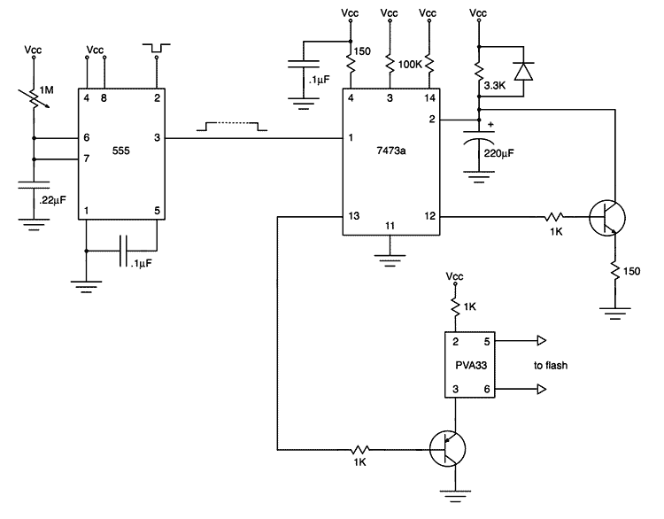
My first project after assembling an electronic design lab was to build a flash trigger that I could use for high-speed photography. I thought it would be useful to share not only the finished product but also the reasoning...
This circuit utilizes an MC3392 low-side protected switch in conjunction with an MC1455 timing circuit to create a dimmer control for automotive instrumentation panel lamps. The brightness of incandescent lamps is adjustable through Pulse Width Modulation (PWM) applied to...
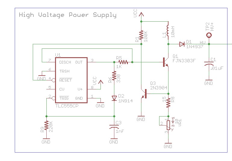
The design involves using a 555 timer as an oscillator in the high voltage power supply section. There is a query regarding the possibility of altering the design to utilize an output from a microcontroller to generate an oscillating...
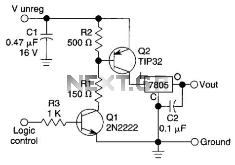
A logic level can control a 7805 regulator with this circuit. Q2 is a series switching transistor controlled by Q1. Q1 is turned on by a logic voltage to its base. This circuit utilizes a 7805 voltage regulator, which is...
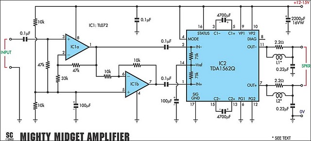
It is based on a Philips class-H audio amplifier IC and can deliver 36W RMS or 70W music power, all from a 13.8V supply. The Mighty Midget Amplifier can provide approximately 36W RMS continuous power into a 4-ohm load...