
7805 Turn-On Circuit Circuit

This circuit utilizes a 7805 voltage regulator, which is designed to output a stable 5V supply from a higher input voltage. The control mechanism is implemented via two transistors, Q1 and Q2. Q1 functions as a control switch that is activated by a logic-level voltage applied to its base. When this voltage is present, Q1 enters the saturation region, allowing current to flow from its collector to its emitter. This action effectively turns on Q2, which is configured as a series switching transistor.
Q2, when activated by Q1, connects the output of the 7805 regulator to the load. This configuration enables the circuit to control the power delivery to the load based on the logic-level signal applied to Q1. The 7805 regulator maintains a constant 5V output as long as the input voltage remains within the specified range and the load does not exceed its current rating.
In practical applications, this circuit can be used in microcontroller-based systems where a digital output pin can control the power to various peripherals or components. The use of transistors allows for efficient switching, minimizing power loss and heat generation compared to mechanical relays. Proper biasing of the transistors is essential to ensure reliable operation, and appropriate resistor values should be selected to limit the base current for Q1 while ensuring that Q2 can handle the load current without entering the saturation region excessively.
Additionally, it is advisable to include bypass capacitors near the input and output of the 7805 to stabilize the voltage and filter out noise, ensuring clean power delivery to the connected load. A logic level can control a 7805 regulator with this circuit. Q2 is a series switcliing transistor controlled by Ql. Ql is turned on by a logic voltage to its base.
Related Circuits
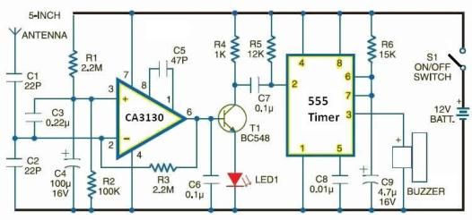
Cellular phone detector circuit schematic using common electronic parts The cellular phone detector circuit is designed to identify the presence of a cellular phone within a specified range. This circuit utilizes basic electronic components, making it accessible for hobbyists and...
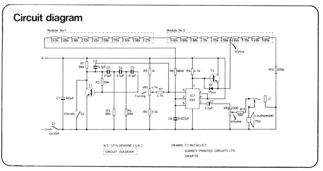
The 900 Hz tone is generated using an LC oscillator. The inductive component, "L," is provided by the inductance of the oscillator's output coupling transformer T1. This configuration is a variation of one of the two standard Hartley oscillator...
The topic of alternative keyboard layouts has gained traction due to advancements in Software and MIDI technology, making it practical to explore different configurations. This post aims to clarify what alternative keyboard layouts are, distinct from other methods of...
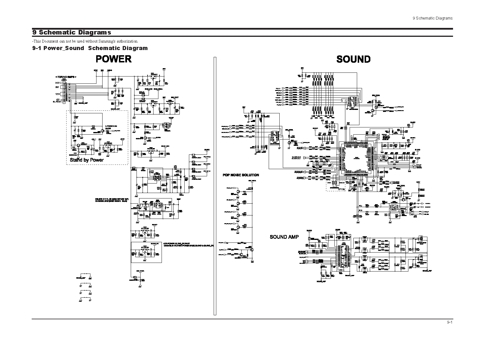
Samsung C3330 Circuit Diagram Download Manual PDF Download. The Samsung C3330 circuit diagram serves as a comprehensive reference for understanding the electronic architecture of the device. This schematic provides detailed insights into the interconnections between various components, including the microcontroller,...
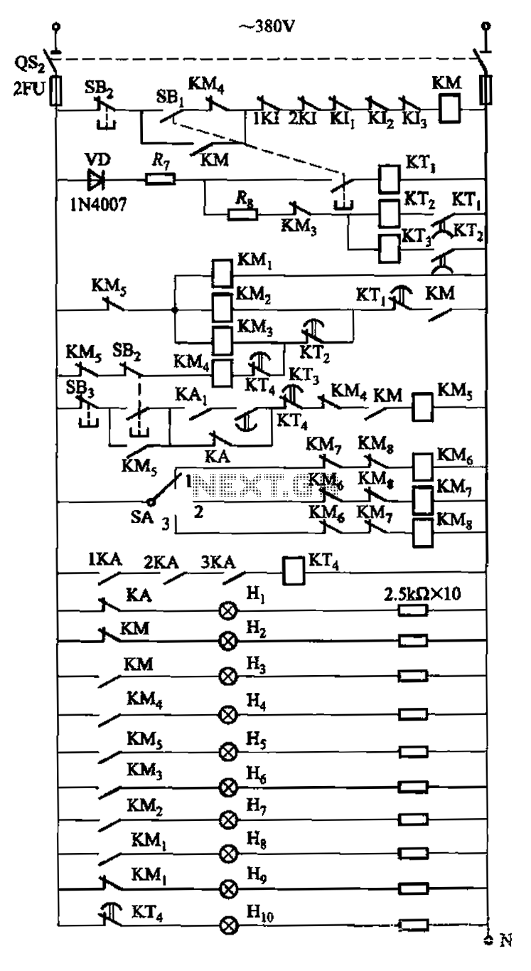
The circuit is illustrated. A motor utilizes series resistance in the rotor winding for starting. The drawing includes electrical velocity off the relay KIi ~ KI3 for motor short circuit protection and overcurrent. Additionally, relays 1KI and 2KI provide...
The bearing fault detection circuit comprises bearing detection sensors, a signal processing circuit, and a sound and light circuit. The signal processing circuit includes the input socket XS, a voice integrated circuit IC1, capacitors C1 to C3, resistors R1,...