
3V FM Transmitter

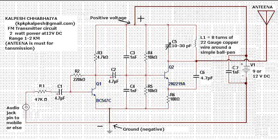
The 3V FM transmitter circuit is designed to operate at a low voltage, making it suitable for battery-powered applications. The circuit typically consists of a few essential components, including an oscillator, modulator, and amplifier, which work together to generate and transmit frequency-modulated signals.
The core of the transmitter is often built around a transistor, which serves as the main amplifying element. The oscillator circuit can be constructed using a combination of capacitors, resistors, and inductors to achieve the desired frequency range, typically within the FM band (88 MHz to 108 MHz). The modulation of the audio signal onto the carrier wave is accomplished by varying the base current of the transistor, which alters the output frequency in accordance with the input audio signal.
To ensure proper operation, the circuit may include additional components such as a low-pass filter to eliminate unwanted harmonics and a power supply circuit that stabilizes the voltage to the required 3V. The antenna design is also critical, as it affects the transmission range and quality of the FM signal. A simple wire antenna can be used for short-range applications, while a more sophisticated design may be employed for extended reach.
The parts list for this circuit typically includes a few common electronic components: a transistor (such as a BC547 or similar), resistors, capacitors, an inductor, and an audio input jack. Proper assembly and tuning of the circuit are essential to achieve optimal performance and clear audio transmission. With careful construction, this 3V FM transmitter can effectively broadcast audio signals over a short distance, making it an excellent project for hobbyists and electronics enthusiasts.3V FM Transmitter Circuit This project provides the schematic and the parts list needed to construct a 3V FM Transmitter. This FM transmitter is.. 🔗 External reference
Related Circuits
This schematic represents an FM transmitter capable of delivering an output power ranging from 3 to 3.5 watts, operational within the frequency band of 90 to 110 MHz. While the circuit exhibits reasonable stability, a Phase-Locked Loop (PLL) can...
Constructing an FM transmitter for the first time can be challenging due to confusion regarding the necessary components, parts, design, PCB layout, and transmission aspects. An FM transmitter is an electronic device that encodes audio signals into radio frequency waves,...
The site features several low-power transmitters, but until now, there has been no receiver. This circuit can be utilized to scan an area or room, indicating whether a surveillance device is active. The challenge in creating an effective detector...
Power supply: 12-14 V stab., 100 mA. RF power: 400 mW. Impedance: 50-75 ohm. Frequency range: 87.5-108 MHz. Modulation: wideband FM. Connect the 6 V / 0.1 A bulb to the output and use R1 to tune the right...
This circuit is designed for precise centigrade temperature measurement. It features a transmitter section that converts the sensor's output voltage, which is proportional to the measured temperature, into frequency. The output frequency bursts are transmitted through the mains supply...
This house FM transmitter for your stereo or any other amplifier provides good signal strength up to a distance of 500 meters with a power output of approximately 200 mW. It operates on a 9V battery. The audio-frequency modulation...