
Simple Long Range FM Transmitter with 2 Watt Power and 1-2 KM Range

An FM transmitter is an electronic device that encodes audio signals into radio frequency waves, allowing for wireless transmission of sound. The basic components required for assembling an FM transmitter include an audio source, an oscillator, a modulator, an amplifier, and an antenna.
The audio source can be any device that outputs audio signals, such as a microphone or an audio player. The oscillator generates a carrier wave at a specific frequency, which is typically in the FM radio band (88 MHz to 108 MHz). This frequency is crucial as it determines the channel on which the transmitter will broadcast.
The modulator is responsible for varying the frequency of the carrier wave based on the audio input. This modulation process encodes the audio signal onto the carrier wave, allowing it to be transmitted over the air. Common modulation techniques used in FM transmitters include direct frequency modulation and phase modulation.
The amplifier boosts the modulated signal to ensure it can travel a sufficient distance. This step is essential, as the output power of the transmitter must meet regulatory standards while maintaining signal clarity. The final component, the antenna, radiates the modulated carrier wave into the surrounding environment, enabling it to be received by FM radios.
When designing the PCB for an FM transmitter, attention should be paid to the layout to minimize interference and optimize performance. Components should be placed to reduce signal loss and ensure a stable power supply. Additionally, proper grounding techniques should be employed to prevent noise in the audio signal.
In summary, building an FM transmitter involves a clear understanding of the components and their functions, along with careful design considerations for the PCB layout to achieve effective transmission of audio signals.We know that building of Fm transmitter for first time is quite hard and we get confused about the components, parts, design, pcb, transmis.. 🔗 External reference
Related Circuits
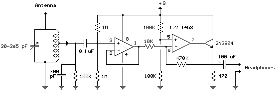
The following schematic illustrates the Simple Op-Amp Radio Circuit Diagram sourced from bowdenshobbycircuits.info. This Simple Op-Amp Radio essentially functions as a crystal radio. The Simple Op-Amp Radio Circuit utilizes an operational amplifier (op-amp) to enhance the performance of a basic...
This is a schematic diagram of a micropower voltage-controlled oscillator circuit. This circuit can generate square and triangle wave outputs and only requires minimal power. The micropower voltage-controlled oscillator (VCO) circuit is designed to produce both square and triangle waveforms,...
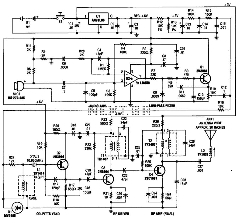
This tracking transmitter consists of four distinct subassemblies: a free-running multivibrator, a transmit switch, an audio-tone generator, and an FM transmitter. The multivibrator, which produces a pulse width with a pulse separation of 1500 ms, is built around Q1...
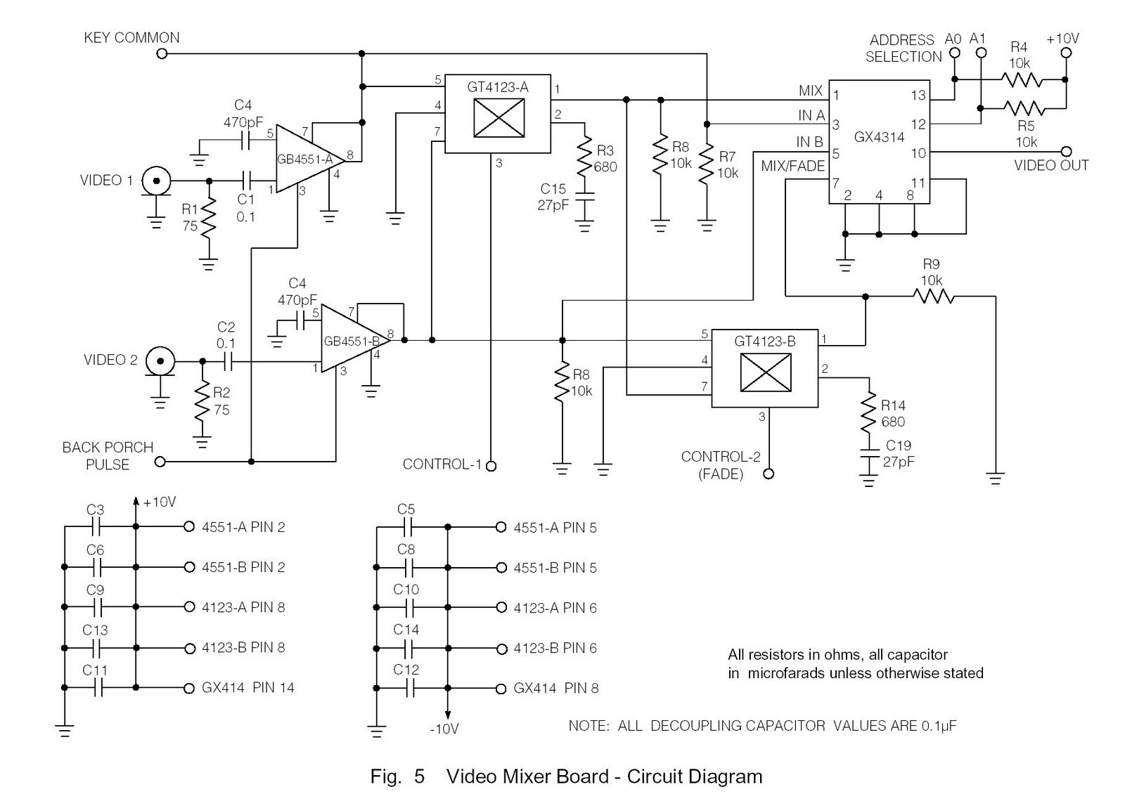
Circuit diagram of marine TV dish. Circuit diagram of marine TV dish, circuit diagram of marine TV dish, 12V DC to 120V AC inverter circuit diagram PDF, 12V DC to 120V AC inverter circuit diagram PDF. The circuit diagram for...
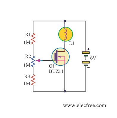
Changing the value of R2 alters the intensity of the lamp in this circuit, demonstrating the utility of a MOSFET as a variable resistor. An N-Channel Power MOSFET, designated as Q1, is utilized in the circuit. The specific part...

A high-quality QRP transmitter, named NEXUS 6, is designed to explore issues related to extremely narrow bandwidth communication. This device is not merely a simplified version of a QRP transmitter; it aims to create a cost-effective system that can...