
3v fm transmitters circuit diagram

The described setup involves an FM transmitter and an FM radio, where the transmitter is designed to operate within the FM band, specifically between 89 MHz and 90 MHz. The procedure begins with positioning the transmitter at a distance of approximately 10 feet from the radio. This distance is critical to minimize interference from harmonics generated by the transmitter, which can complicate the tuning process.
The transmitter includes a coil, which is a key component in the LC (inductor-capacitor) circuit responsible for generating the desired frequency. The coil windings should be carefully separated by about 1 mm to prevent any unintended coupling between turns, which could affect the performance and frequency stability of the transmitter.
A trim capacitor is present in the circuit, and its capacitance can be adjusted using a small screwdriver. It is important to remove the screwdriver after each adjustment to avoid introducing stray capacitance, which could lead to inaccurate tuning. Alternatively, a plastic screwdriver can be used, as it is less likely to introduce stray capacitance.
The tuning process involves adjusting the trim capacitor, which has a capacitance range from 6 pF to 45 pF. A full turn of the trim capacitor will span this entire range, but since the FM band occupies only a fraction of this range, it is recommended to adjust the capacitor in smaller increments of 5 to 10 degrees. This methodical approach helps in fine-tuning the frequency to achieve optimal performance.
If difficulties arise in locating the transmitting frequency, the assistance of a second person can be beneficial. This person can actively tune the FM radio while the primary user makes adjustments to the trim capacitor, allowing for real-time feedback and easier identification of the desired frequency.
Overall, the tuning procedure requires patience and careful adjustments, but following these guidelines will facilitate the successful operation of the FM transmitter and enhance the listening experience on the FM radio.Place the transmitter about 10 feet from a FM radio. Set the radio to somewhere about 89 - 90 MHz. Walk back tothe FM transmitter and turn it on. Spread the winding of the coil apart by approximately 1mm from each other. No coilwinding should be touching another winding. Use a small screw driver to tune the trim cap. Remove the screwdriverfrom the trim screw after every adjustment so the LC circuit is not affected by stray capicitance. Or use a plasticscrewdriver. If you have difficulty finding the transmitting frequency then have a second person tune up and downthe FM dial after every adjustment. One full turn of the trim cap will cover its full range of capacitance from 6pF to 45pF. The normal FM band tunes in over about one tenth of the full range of the tuning cap. So it is best to adjust it in steps of 5 to 10 degrees at each turn. So tuning takes a little patience but is not difficult. The reason that there must be at least 10 ft. separation between the radio and the FM transmitter is that the FM transmitter emits harmonics; it does not only emit on one frequency but on several different frequencies close to each other.
You should have little difficulty in finding the Tx frequency when you follow this procedure. 🔗 External reference
Related Circuits
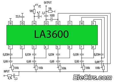
Circuit LA3600 5 Band Equalizer Circuit Schematics. One type of tone control in audio electronics is the graphic equalizer. Graphic equalizers can be categorized into two types: bar and other configurations. The LA3600 circuit is a 5-band graphic equalizer designed...
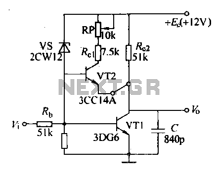
Various sawtooth voltage generators utilize the principle of capacitor charging and discharging to produce sawtooth waveforms in both forward and reverse directions. A simple sawtooth voltage generator circuit is straightforward in design; however, it suffers from poor linearity in...
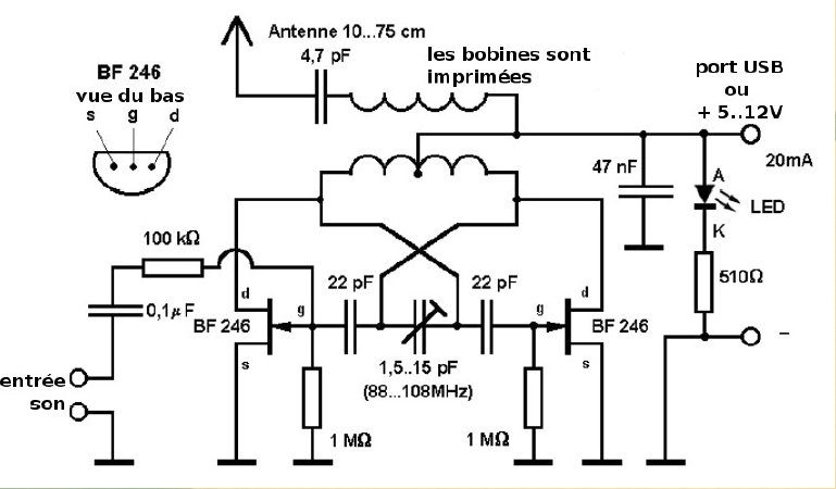
Here is a small FM transmitter circuit designed for desktop or laptop use, allowing users to enjoy movies and music from a distance. This USB-powered FM transmitter connects to a computer or MP3 player and broadcasts on a tape...
This is a single alarm circuit. The circuit includes automatic exit and entry delays, a timed bell cut-off, and a system reset. It has provisions for normally open and normally closed inputs. The single alarm circuit is designed to provide...
This is quite a nice chip, and has myriad uses, but we only need it to perform one function here. Since most game systems output the composite sync information along with the NTSC video output, and since most RGB...
In this circuit, the alarm is activated under four different conditions: 1. When light falls on LDR1 (located at the entry to the premises). 2. When light falling on LDR2 is obstructed. 3. When door switches are opened or...