
LM1881 circuit

The LM1881 is a versatile sync separator integrated circuit designed to extract synchronization signals from composite video signals. In this application, it is utilized to separate the composite sync information from the NTSC video output provided by game systems, which is essential for compatibility with RGB monitors that require a clean sync signal without accompanying video data.
The circuit configuration involves connecting the LM1881 to the composite video output of the game system. The chip requires a few passive components for proper operation: two capacitors and one resistor. The first capacitor is typically connected to the input pin of the LM1881, filtering the input signal to ensure that only the necessary sync pulse is processed. The second capacitor is used to decouple the power supply, providing stability to the chip during operation. The resistor is often placed in series with the output to limit the current and protect the subsequent circuitry.
When the composite video signal is fed into the LM1881, it analyzes the waveform and extracts the horizontal and vertical sync pulses. These pulses are then outputted as separate signals, which can be directly interfaced with an RGB monitor. The LM1881 is designed to operate from a single power supply, typically ranging from 5V to 12V, making it suitable for various applications.
The compact nature of the LM1881 allows it to be easily integrated into a small form factor, such as a DB-9 hood, which is advantageous for applications where space is limited. This simplicity and effectiveness make the LM1881 an ideal choice for projects requiring sync signal extraction from composite video sources.
In summary, the circuit utilizing the LM1881 efficiently separates sync signals from NTSC video outputs, ensuring compatibility with RGB monitors, and consists of minimal components for ease of implementation.This is quite a nice chip, and has myriad uses, but we only need it to perform one function here. Since most game systems output the composite sync information along with the NTSC video output, and since most RGB monitors will not accept this extraneous info along with the sync, we need to remove the video signal. The LM1881 does an admirable job of this. It's a dead easy circuit - one small chip, two small capacitors and a small resistor. As the below pic shows, it's small enough to wedge into a DB-9 hood. 🔗 External reference
Related Circuits
This transmitter emits an FM signal within the 88 to 108 MHz frequency range, featuring a tone of 19 kHz. This tone can activate the FM MPX pilot carrier indicator, allowing interfacing with external devices. L4 is designed for...
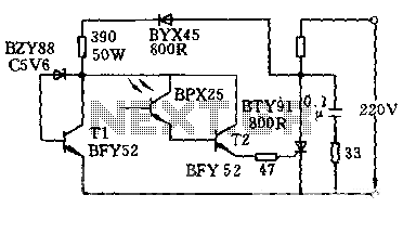
The circuit is designed to activate when the light intensity exceeds 700lx. In this configuration, a phototransistor and the BFY52 transistor are used to trigger the BTY91 thyristor with a current. When light strikes the phototransistor, a positive trigger...
This design is based on a publication by Milan Lulic in the German magazine elektroModell. Lulic's design utilizes surface mount technology (SMT), while this version employs standard off-the-shelf components, making it more accessible for hobbyists. For those interested in...
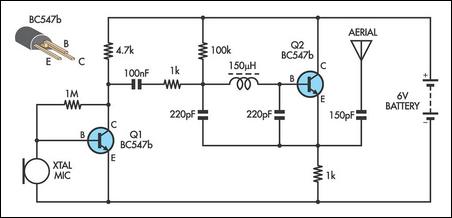
This AM transmitter is designed for simplicity, featuring an untapped inductor with a single winding. The inductor can be easily sourced as a standard RF choke, such as the Jaycar Cat LF-1536. To minimize the circuit size, a conventional...
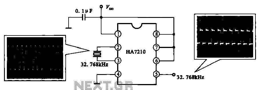
This circuit illustrates a 32.768 kHz micro-power clock oscillator, suitable for use in mobile phones, laptop computers, and home appliances. It generates a clock signal that can be utilized in various applications. The 32.768 kHz micro-power clock oscillator circuit is...
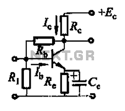
Basic reference transistor bias circuit - Mixed Negative feedback The basic reference transistor bias circuit utilizing mixed negative feedback is a fundamental electronic configuration designed to stabilize the operating point of a transistor. This circuit typically employs a combination of...