
5 Band Equalizer Circuit using

The LA3600 circuit is a 5-band graphic equalizer designed to adjust audio frequency levels within a specified range, allowing for enhanced sound customization. This circuit utilizes operational amplifiers to process audio signals, providing users with the ability to boost or cut frequencies across five distinct bands. Each band typically corresponds to a specific frequency range, such as low, mid-low, mid, mid-high, and high frequencies.
The schematic for the LA3600 will include key components such as resistors, capacitors, and potentiometers. The resistors are used to set gain levels for each frequency band, while capacitors help in filtering the audio signal to isolate the desired frequencies. Potentiometers, often referred to as sliders in graphic equalizers, allow users to manually adjust the gain for each band, providing a visual representation of the adjustments made.
Power supply requirements for the LA3600 circuit are also critical, as the operational amplifiers require a stable voltage to function correctly. Typically, a dual power supply configuration (positive and negative voltage rails) is employed to ensure optimal performance of the op-amps.
The layout of the circuit should be carefully designed to minimize noise and interference, which can affect audio quality. Proper grounding techniques and the use of shielded cables can further enhance the performance of the LA3600 equalizer.
In conclusion, the LA3600 5-band graphic equalizer circuit provides an effective means for audio signal manipulation, allowing for tailored sound experiences in various audio applications.Circuit LA3600 5 Band equalizer Circuit schematics Circuit Electronics, One type of regulator of tone / tone controls are the audio Graphic Equalizer. audio Graphic equalizer have 2 kinds in my opinion. Namely audio Graphic equalizer Bar a.. 🔗 External reference
Related Circuits
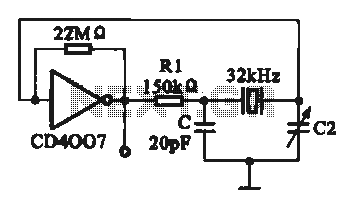
A 32 kHz clock oscillator is essential for digital circuits, as depicted in the schematic. The 32 kHz crystal clock oscillator serves to provide a time reference signal for the digital circuit. It utilizes a CMOS integrated circuit, specifically...
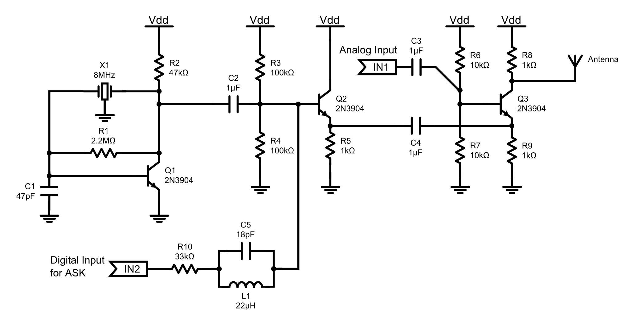
This is an 8MHz amplitude modulated (AM) radio transmitter designed primarily for practical applications and as an educational exercise in electronics. The objective was to create a simple radio transceiver that could be used in future projects requiring basic...
A simple CATV upstream fiber optic receiver utilizes DC pilot automatic gain control (AGC). Upstream fiber links in a community antenna television (CATV) system are often challenging to align correctly. Set-top boxes and cable modems use "long-loop" AGC. Additionally,...
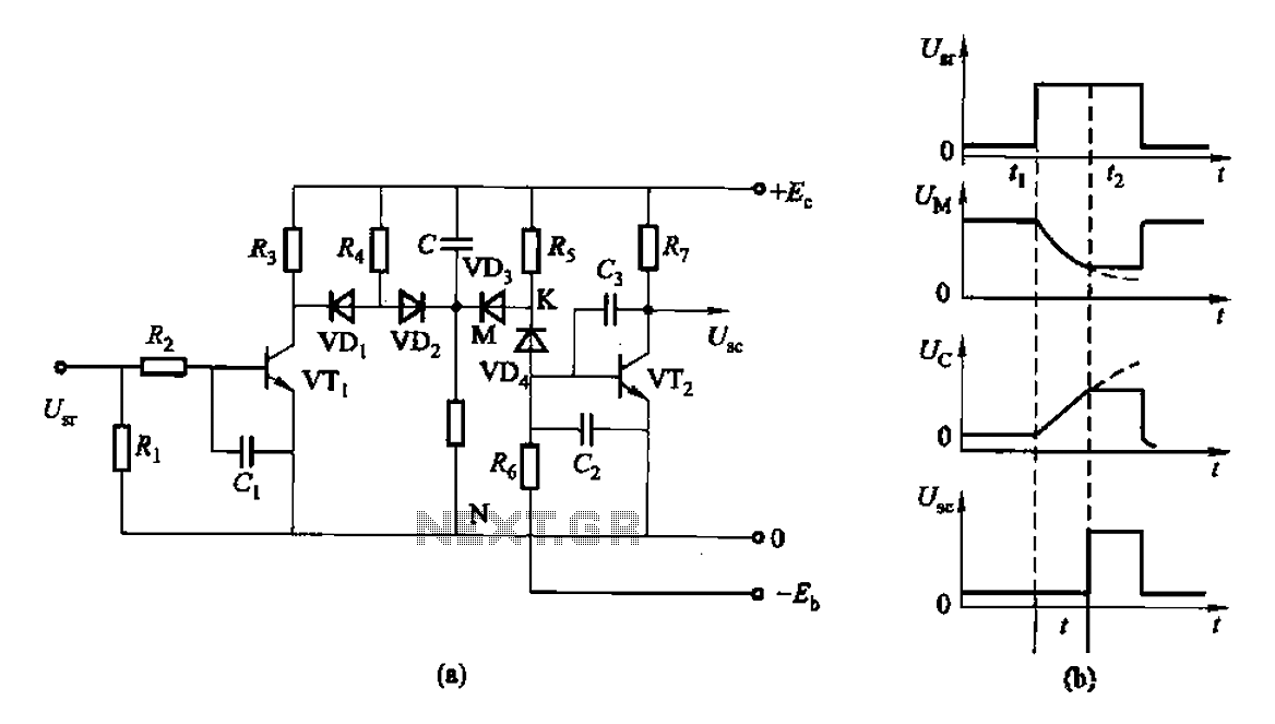
This is a control rechargeable delay circuit. Under normal circumstances, when there is no input signal, the transistor VTi is off. VTz is conducting, resulting in a low output potential (U). When a signal is applied, VTi turns on,...
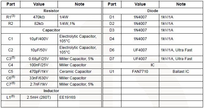
The FAN7710 Ballast Control IC for Compact Fluorescent Lamps, developed using Fairchild's unique high-voltage process and system-in-package (SiP) concept, enables the design of a simple and low-cost fluorescent lamp driver electronic project. The FAN7710 ballast control manages internal high-voltage...
The multi-channel temperature measurement circuit is illustrated in the figure. The core of the test circuit comprises a 555 one-shot delay circuit. When the button is pressed, the output pin of the 555 timer (IC1) goes high due to...