
Low frequency lamp flasher-relay driver

The low-frequency warning device circuit typically consists of an oscillator, which can be implemented using a 555 timer IC configured in astable mode. The frequency of oscillation can be adjusted by selecting appropriate resistor and capacitor values connected to the timer. The square wave output from the 555 timer is then used to control the operation of two incandescent lamps.
In the circuit, the output pin of the timer is connected to the base of a transistor, which acts as a switch to drive the lamps. When the square wave output goes high, the transistor is turned on, allowing current to flow through the first lamp, illuminating it. As the output transitions to low, the transistor turns off, and the first lamp goes out. Simultaneously, a second transistor can be used to control the second lamp, ensuring that it turns on when the first lamp is off, creating an alternating flashing effect.
To enhance the circuit's performance, diodes may be employed to prevent back EMF from the inductive load (if relays are used) from affecting the oscillator. Additionally, capacitors can be added for stability, and resistors can be employed for current limiting to protect the lamps and transistors from excessive current.
The design of this circuit is straightforward, making it suitable for applications such as warning signals in various environments, where visual alerts are necessary. The alternating flash of the lamps serves to attract attention effectively, making it an efficient warning device.This circuit is a low frequency warning device. The output of the oscillator is a square wave that is used to drive lamps or small relays The circuit alternately flashes two incandescent lamps.
Related Circuits
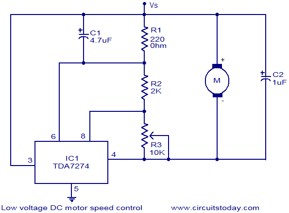
The circuit diagram illustrates a low voltage/low power DC motor speed controller utilizing the TDA 7274 integrated circuit from ST Microelectronics. The TDA 7274 is designed for low voltage and low power applications, featuring an internal voltage reference, a...
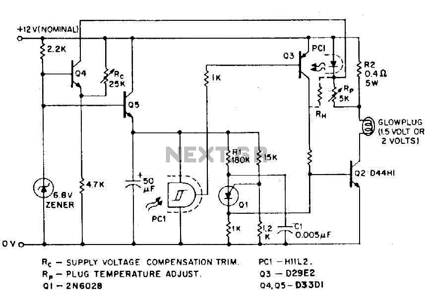
The circuit is designed for model airplanes, boats, and cars that utilize glow plugs for their miniature internal combustion engines (ranging from 0.1cc to 15cc). These engines are equipped with heavy batteries, high-tension coils, and capacitors necessary for classic...
Stationary - MOPLL & Silicon Tuner TUA6020 2 Band TV Tuner Mixer-Oscillator-PLL with balanced IF-Amplifier. The TUA6020 device integrates a digitally programmable Phase Locked Loop (PLL) with a mixer-oscillator block that includes two balanced mixers and oscillators suitable for...
Many battery-powered devices use two AA alkaline cells. Often, it is not apparent when it is time to replace the batteries until the device powered by them ceases to function. In battery-powered devices that utilize two AA alkaline cells, it...
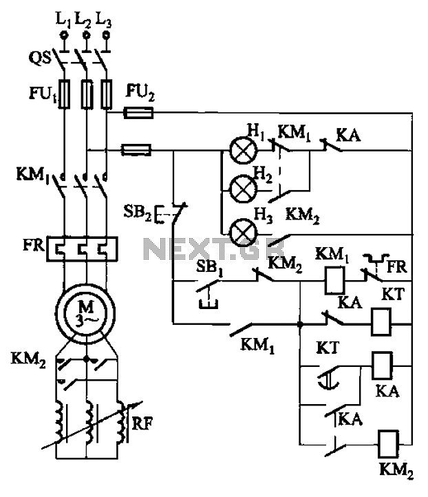
The circuit depicted in Figure 3-165 utilizes a time relay (KT) for controlling the start-up time. Indicator light Hi serves as the power indicator, H2 is designated for the start lights, and H3 functions as the running lights. The circuit...
The ICL7665S Super CMOS Micropower Over/Under Voltage Detector features two low-power, individually programmable voltage detectors integrated on a single CMOS chip. It typically requires 3 µA for operation and is designed for battery-operated systems and instruments that need high...