
3W FM Transmitter circuit

The FM transmitter circuit typically consists of several key components, including an oscillator, modulator, and power amplifier. The oscillator generates a carrier frequency within the specified range, while the modulator encodes the audio signal onto the carrier wave. The power amplifier then boosts the modulated signal to the desired output power level.
In this design, the oscillator may employ a Colpitts or Hartley configuration, which is known for its stability and ease of tuning. The frequency can be adjusted using variable capacitors or inductors, allowing for fine-tuning within the 90 to 110 MHz range.
The modulator section can utilize a transistor or an integrated circuit that modulates the amplitude or frequency of the carrier signal based on the input audio signal. This modulation is crucial for transmitting audio over the FM band effectively.
The power amplifier is responsible for increasing the output signal to the specified power level. It may utilize a push-pull configuration to improve efficiency and linearity, ensuring minimal distortion of the audio signal during transmission.
Incorporating a PLL into this circuit can significantly improve frequency stability and drift compensation. The PLL can lock onto the desired frequency and maintain it against variations in temperature or component aging. This addition would enhance the overall performance of the FM transmitter, making it more reliable for consistent broadcasting.
Additional components such as filters may be included to suppress unwanted harmonics and ensure compliance with regulatory standards for FM transmission. Proper grounding and layout considerations are essential to minimize interference and maintain signal integrity throughout the circuit.This is the schematic for an FM transmitter with 3 to 3.5 W output power that can be used between 90 and 110 MHz. Although the stability isn`t so bad, a PLL can be used on this circuit.. 🔗 External reference
Related Circuits

The FAN4810 operates as a continuous conduction mode (CCM) power factor correction (PFC) controller. It features an internal safety detection mechanism that prevents circuit malfunction due to component damage. The device has a power-handling capability of up to 1A,...
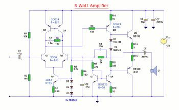
The diagram illustrates a 5W audio amplifier circuit constructed using power transistors BD139 and BD140 for the final amplification stage. This compact amplifier serves as a general-purpose amplifier suitable for applications such as computer audio, radio, MP3 players, and...
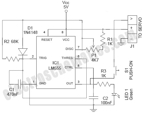
A servo is an error-sensing feedback control mechanism used to correct the performance of a system. A servo motor is a DC motor equipped with a servo mechanism. A servo motor is an electromechanical device that utilizes a closed-loop control...
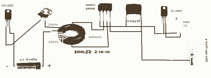
Second Stage Joule Thief Circuits The second stage Joule Thief circuit is an advanced iteration of the basic Joule Thief design, which is primarily used to extract energy from low-voltage sources, such as depleted batteries. This circuit is particularly effective...
This circuit is designed to generate audio musical notes that can be heard from a distance of up to 10 meters. It consists of two main components: an infrared (IR) music transmitter and an IR music receiver. The IR...
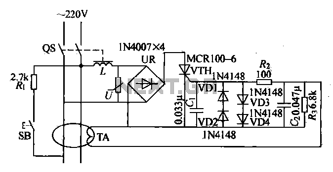
Current leakage protection is the most commonly used and effective leakage protection device. Current leakage protectors can be divided into electromagnetic and electronic types. The zero-sequence current transformer serves as the detection element, while electromagnetic leakage protection uses a...