
3W Stereo Amplifier schematic

The 3-watt stereo amplifier circuit based on the MAX9710 IC is designed for applications requiring compact audio amplification. The MAX9710 is particularly advantageous due to its ability to deliver adequate power to 4-ohm speakers, ensuring clear audio playback without distortion at moderate volume levels. The operational voltage range of 4.5V to 5.5V allows for flexibility in power supply selection, making it suitable for battery-operated devices.
In this circuit, the MAX9710's thermal overload protection feature safeguards the amplifier from damage due to excessive heat, enhancing its reliability in various operating conditions. The circuit can be powered by a regulated 5V DC source, which is commonly available in many electronic devices. Alternatively, using a 6V battery with an IN4007 diode ensures that the voltage supplied to the amplifier remains within the acceptable range, despite the inherent voltage drop across the diode.
The overall design of the 3-watt stereo amplifier circuit prioritizes efficiency and performance, making it an excellent choice for integration into portable audio devices. Its compact size and low power requirements make it suitable for use in applications such as portable music players, handheld radios, and other small electronic audio devices. Proper layout considerations, including minimizing trace lengths and ensuring adequate decoupling, are essential for optimal performance and audio fidelity.3 Watt stereo amplifier circuit using MAX 7910 IC. The MAX9710 a stereo audio power amplifier IC capable of delivering 3Watts of out put to 4 Ohm loads. MAX9710 can be operated from a single 4. 5V to 5. 5V power supply, makes it ideal for hand held applications. The IC for3 Watt stereo amplifier circuitalso features thermal overload protection. This3 Watt stereo amplifier circuitis suitable for small power audio devices such as radio sets and portable CD players. 5 V DC power supply is used for powering the3 Watt stereo amplifier circuit. 6V battery with an IN 4007 diode series to the positive terminal of it can also be used instead of 5 V DC supply.
The3 Watt stereo amplifier circuitwill get a supply voltage approximately 5 V after 0. 7 V voltage drop across diode. 🔗 External reference
Related Circuits
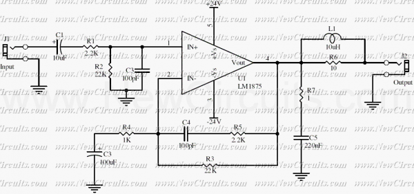
This simple 20 watts audio power amplifier is designed for home-brewed purpose. The L1 should be able to handle a current up to 4A to drive speaker in full load. The distortion is 0.015% @ 1KHz / 20W. This...
During a telephone conversation with a distant subscriber, it is common to experience frustration due to the faintness of the voice, making it difficult to understand. To address this issue, a circuit for an inexpensive amplifier is presented. This...
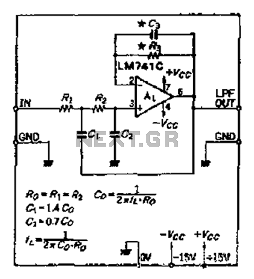
A 12dB/oct Butterworth filter circuit is designed to achieve a flat frequency response. The optimal value for the circuit's Q factor is 0.707, which ensures a flat characteristic. The feedback capacitance must be selected to maintain high capacity and...
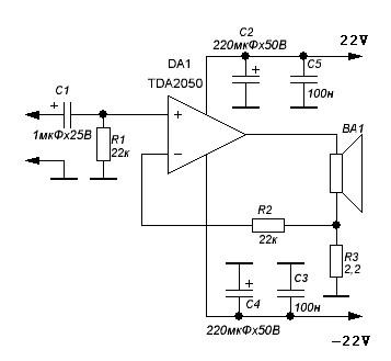
TDA2050 audio amplifier circuit diagram. The circuit incorporates environmental protection, where the output signal travels through connecting cables and the speaker’s network. In this case, the reactance of the circuit section connected to pin 4 of the chip is...
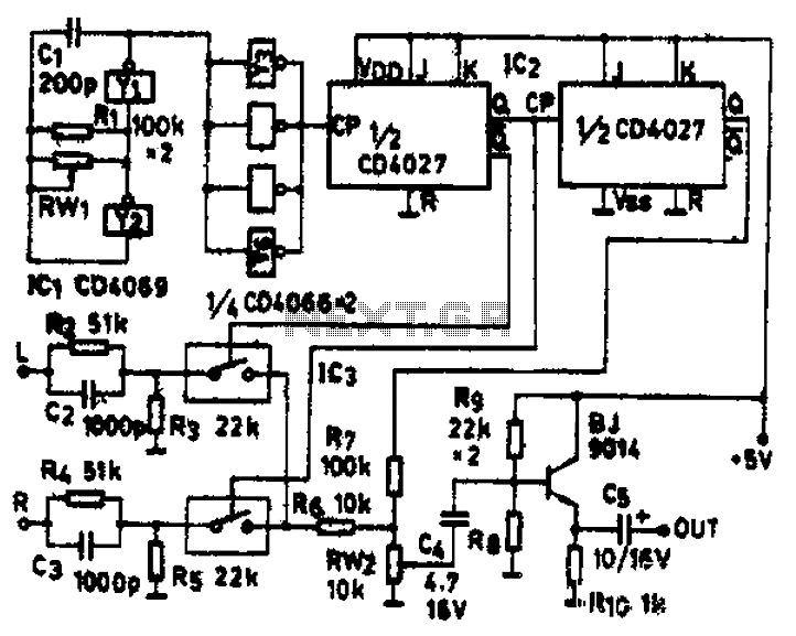
The circuit schematic diagram features IC1 (4069) and components Y1 and Y2, which together form a frequency oscillator operating at 76 kHz. Components Y3 to Y6 provide isolation and shape the output into the IC2 (CD4027) dual JK flip-flop,...
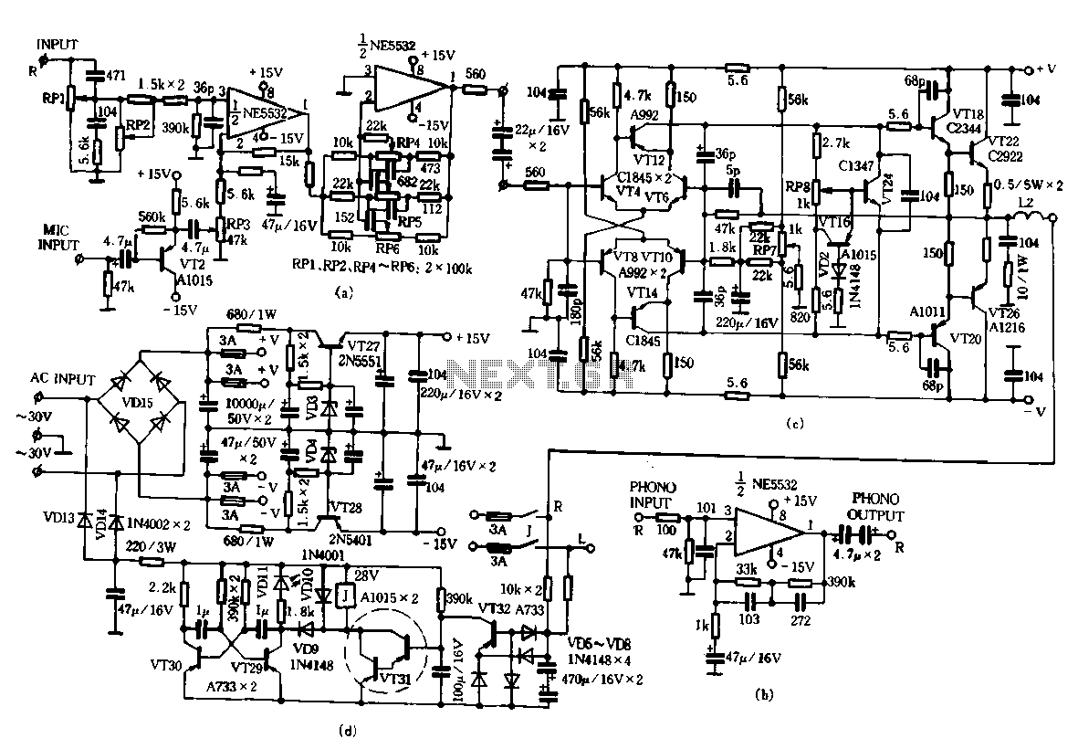
Only the R channel is shown, with the original reference PCB label. Figure (a) illustrates the front tone circuit, which consists of a common negative feedback operational amplifier in an RC circuit configuration. The microphone signal is amplified by...