
4 ~ 20mA transmitter circuit diagram TMP35 temperature

The transmitter's output current can be expressed as a function of the input voltage from the TMP35 sensor, which is a linear temperature sensor providing a voltage output proportional to the temperature. The TMP35 outputs a voltage of 10 mV per degree Celsius, allowing for a direct correlation between temperature and output current. The operational amplifier (OP193) amplifies this voltage signal to the required level, while the REF193 provides a stable reference voltage for accurate current regulation.
The circuit design features two adjustable potentiometers, RP1 and RP2, which are critical for fine-tuning the zero and full-scale outputs. Adjusting RP1 alters the zero-scale output, ensuring that at a specific temperature (usually at the lower end of the temperature range), the output current is precisely set to 4 mA. Similarly, RP2 is used to adjust the full-scale output, ensuring that at the maximum temperature (the upper limit of the intended measurement range), the output current reaches 20 mA.
The inclusion of the Schottky diode (VD1) is significant as it protects the operational amplifier from potential damage due to excessive voltage levels that could occur in an open-loop condition. This diode allows for fast switching and low forward voltage drop, making it an ideal choice for this application.
The power supply requirements of +9V to +18V ensure that the circuit operates efficiently while providing sufficient headroom for the operational amplifier and other components. Overall, this TMP35 temperature transmitter circuit is designed to provide a reliable and accurate method for temperature measurement and control in various industrial applications, leveraging the 4 to 20 mA current loop standard widely used in process control systems.4 ~ 20mA constituted by a TMP35 temperature transmitter circuit as shown in FIG. This circuit can be a voltage signal TMP35 output is converted into a standard 4 ~ 20mA current signal, for the use of automated instrumentation, industrial temperature control. Here is 4mA as zero-scale value, 20mA full-scale value. REF193 is 3V reference voltage source, OP193 operational amplifier. RP1, RP2, respectively, and full scale calibration potentiometer zero, both can be adjusted independently of each other. VD1 Schottky diode, which prevents OP193 open loop voltage increases. Preferably the power supply voltage + 9 ~ + 18V. Transmitter output current expression is:
Related Circuits
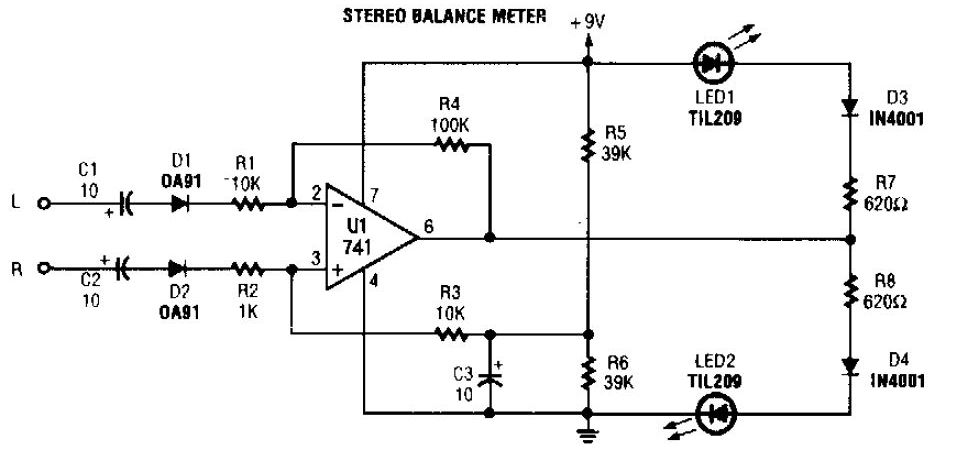
The simplest stereo balance meter circuit schematic available on the internet. When the left and right signals are equal, no output is present from U1 and pin. This stereo balance meter circuit is designed to visually indicate the balance between...
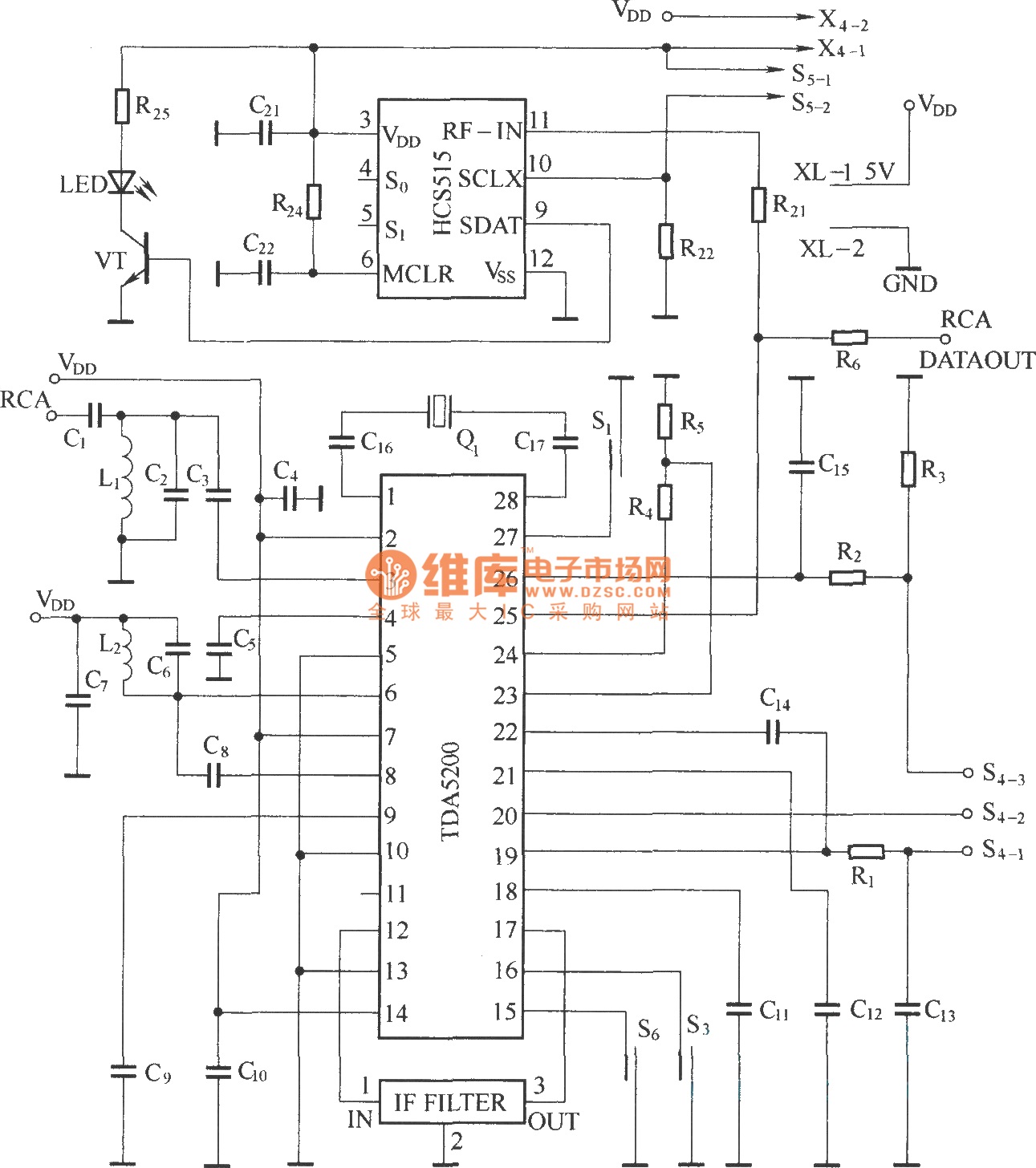
The TDA5200 is a low-power, single-chip ASK superheterodyne receiver circuit. It operates within two frequency blocks: 868 to 870 MHz and 433 to 435 MHz. This circuit is highly integrated, requiring minimal external components while offering excellent functionality. It...
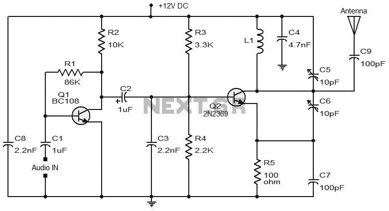
Numerous FM transmitter circuits have been published, and this is another example of a simple two-transistor FM transmitter. The first stage of the circuit is a preamplifier based on transistor Q1. This stage operates as a collector-to-base biased amplifier,...

Remote temperature measurements must be connected to the relevant test instrument using a cable. Typically, a three-core cable is employed: one core for the signal and two for the power supply. If a two-core cable is necessary, one of...
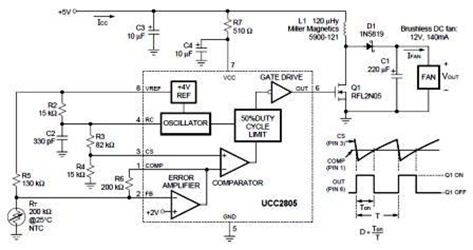
A temperature-controlled pulse-width-modulator (PWM) boost converter circuit diagram is illustrated in the following figure. This boost converter is designed to operate a 12V fan using a 5V supply while maintaining temperature control. The temperature-controlled PWM boost converter circuit operates by...
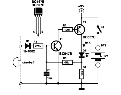
If you are expecting an important visitor but need to step out for a moment, an electronic doorbell memory can be useful to check who rang the bell. An electronic doorbell memory system is designed to capture and store the...